Grow Room Ventilation Troubleshooting Decision Tree
In controlled environment agriculture and indoor craft cannabis cultivation, the atmospheric ventilation system is the physiological lifeline of the crop. While lighting fixtures drive photosynthesis, the ventilation infrastructure regulates the critical gaseous and thermodynamic exchanges that make carbon assimilation possible. When ventilation fails or operates out of calibration, the consequences are immediate and catastrophic: rapid thermal runaway, vapor pressure deficit (VPD) collapse, stomatal closure, powdery mildew proliferation, botrytis bud rot, and telltale terpene odor leaks that compromise operational security.
Diagnosing grow room ventilation failures is often complicated by symptom overlap. A cultivator observing leaf tip curling, stunted transpiration, and rising tent temperatures might reflexively conclude that their inline exhaust fan is undersized and rush to purchase a larger blower. However, the root cause could be an uninsulated duct run creating excessive static pressure resistance, an air-starved passive intake collapsing tent walls, a saturated carbon filter blinding airflow, or an aspirated temperature sensor suffering from severe radiant heat bias. Replacing functional equipment without a systematic diagnosis wastes capital and leaves the underlying mechanical defect uncorrected.
To eliminate guesswork and restore environmental control rapidly, cultivators must approach environmental troubleshooting through a rigorous, algorithmic decision tree. Every physical anomaly in an air-handling system leaves distinct aerodynamic, thermodynamic, and acoustic signatures. By methodically isolating variables across static pressure, volumetric airflow rate (CFM), psychrometric dew point, and motor control electronics, growers can identify the exact failure mode within minutes. In this engineering reference, we present an exhaustive diagnostic framework designed to resolve every common ventilation breakdown encountered in indoor cultivation facilities.
The Master Troubleshooting Variable: Static Pressure Differential
The single most revealing diagnostic variable in any forced-air ventilation system is external static pressure (ESP), measured in inches of water gauge (in. w.g.) or Pascals (Pa). When an environmental anomaly occurs, measuring static pressure upstream and downstream of the fan immediately reveals whether the failure is aerodynamic (excessive resistance from ducting or clogged media) or mechanical/electrical (fan motor failure, incorrect voltage, or controller signaling faults). An inline fan operating against 0.6 in. w.g. of restriction delivers less than 40 percent of its rated free-air CFM, converting wasted electrical energy directly into motor heat.
Before initiating hardware adjustments, technicians must understand the fundamental physical laws governing air movement. Air behaves as an incompressible fluid at the velocities and pressures typical of indoor cultivation. It always follows the path of least resistance, expands as it absorbs sensible heat, and carries latent moisture that dramatically changes its enthalpy and condensation behavior across thermal gradients.
Cultivators must recognize that ventilation problems rarely exist in isolation. A modification made to one section of the air-handling network reverberates through the entire facility. Increasing exhaust fan RPM to evacuate heat, for instance, simultaneously intensifies negative pressure, pulls unconditioned air through building envelopes, alters carbon filter dwell time, and shifts room vapor pressure deficit. Our structured decision tree maps these interconnections, providing clear branching logic from initial physical symptom down to verified corrective action.
Diagnostic Decision Branch 1: Canopy Heat Buildup Despite Maximum Fan RPM
The most frequent ventilation complaint reported by indoor growers is chronic canopy heat buildup, where the exhaust blower runs continuously at 100 percent speed yet grow tent temperatures remain stubbornly above the acceptable vegetative or flowering threshold (28°C to 32°C). When confronted with this symptom, follow this sequential diagnostic branch:
Checkpoint 1.1: Verify Thermal Source vs. Aerodynamic Capacity. Calculate total sensible heat generation within the space. Every Watt of electrical power consumed by LED drivers, luminaires, water pumps, and dehumidifiers generates exactly 3.412 BTUs of sensible heat per hour. If a 4×4 grow tent contains 680 Watts of high-intensity lighting and a 50-pint dehumidifier drawing 420 Watts, total continuous heat output is 3,753 BTU/hr. Evacuating this heat requires a baseline volumetric airflow calculated by the sensible heat equation: CFM = BTU/hr / (1.08 x Delta-T). If the incoming lung room makeup air is 26°C (78.8°F) and target tent temperature is 28°C (82.4°F), Delta-T is only 3.6°F, requiring over 960 CFM of actual airflow! If your makeup air is too warm, no exhaust fan on Earth can cool the tent below the intake air temperature.

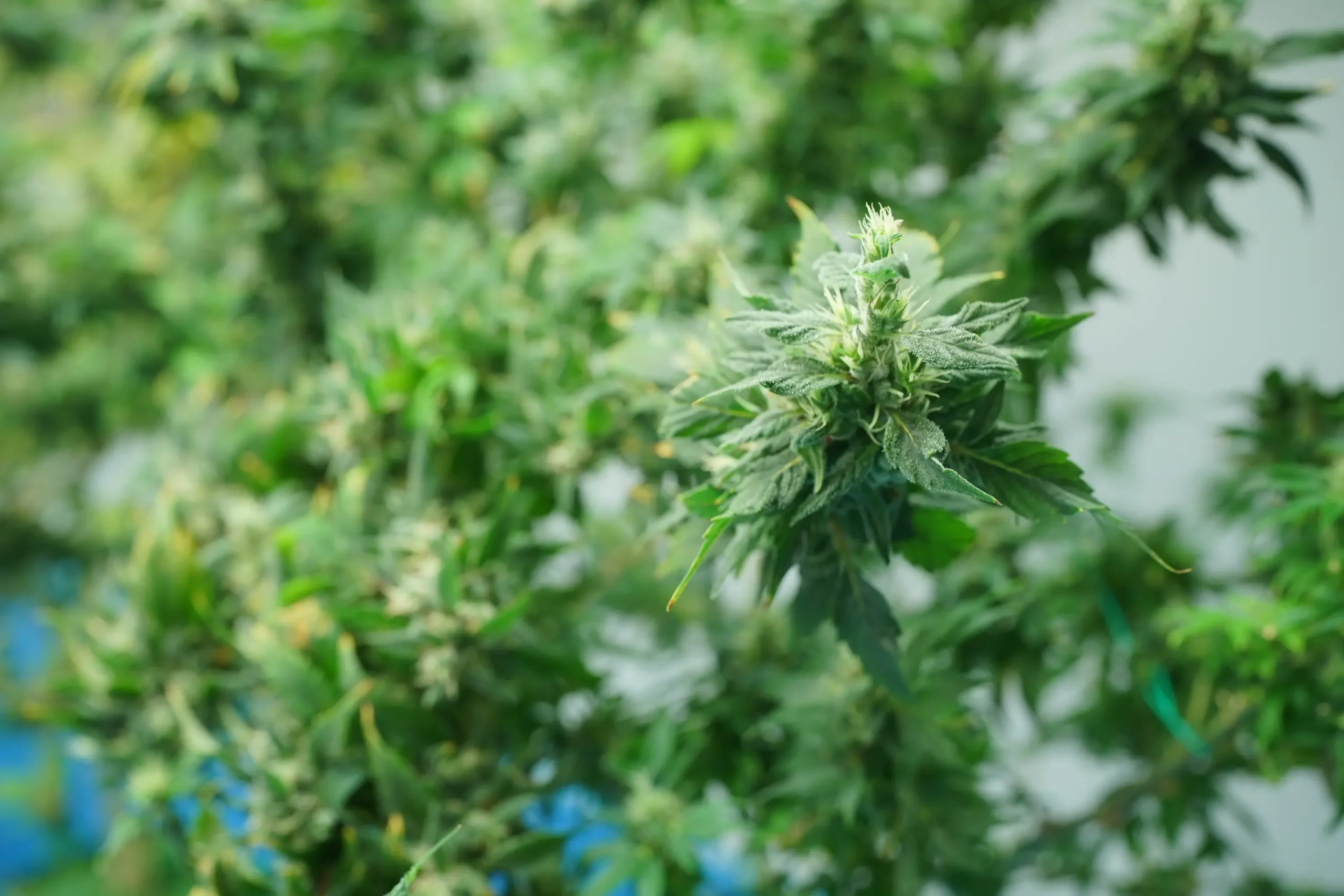
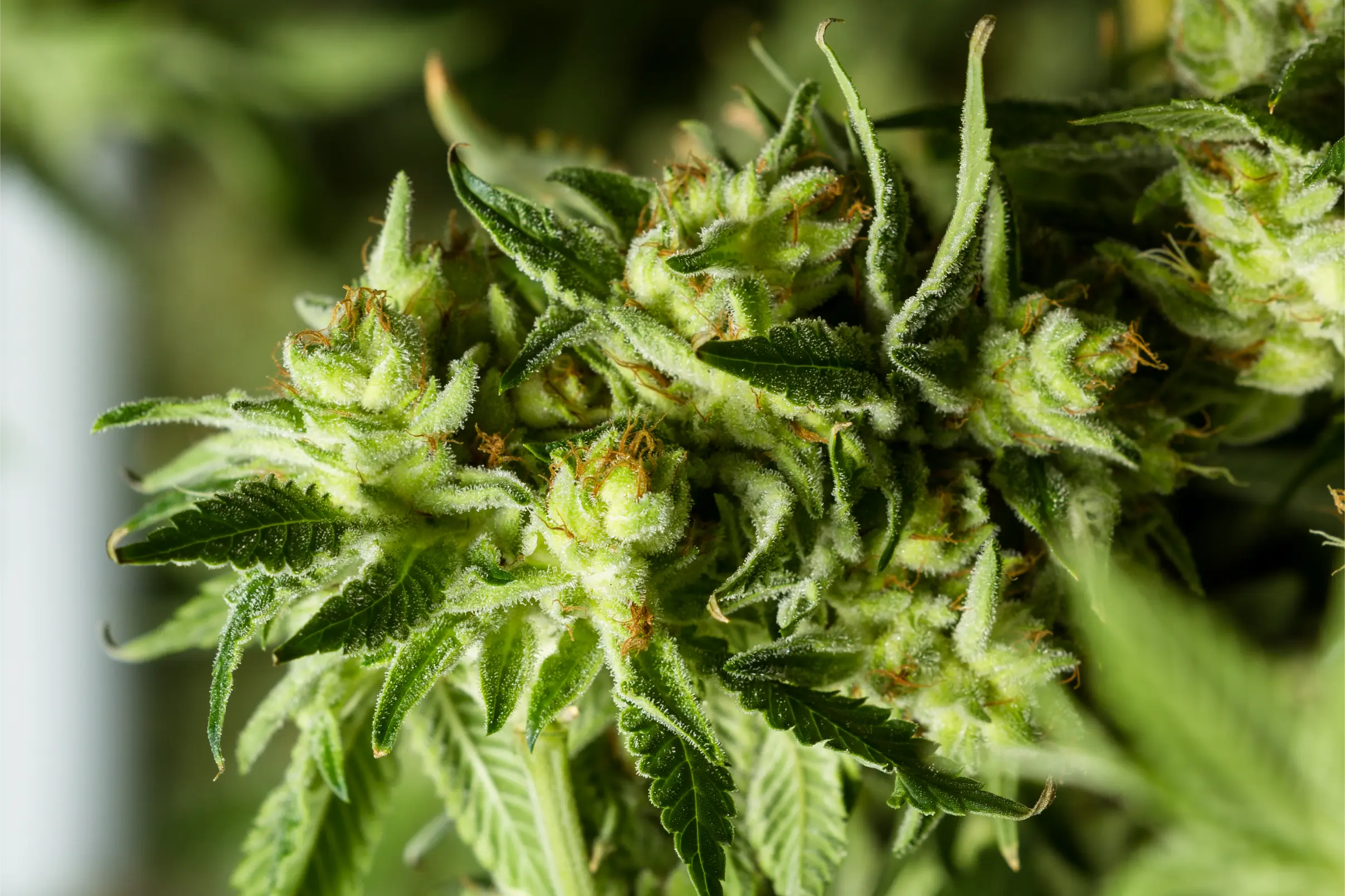
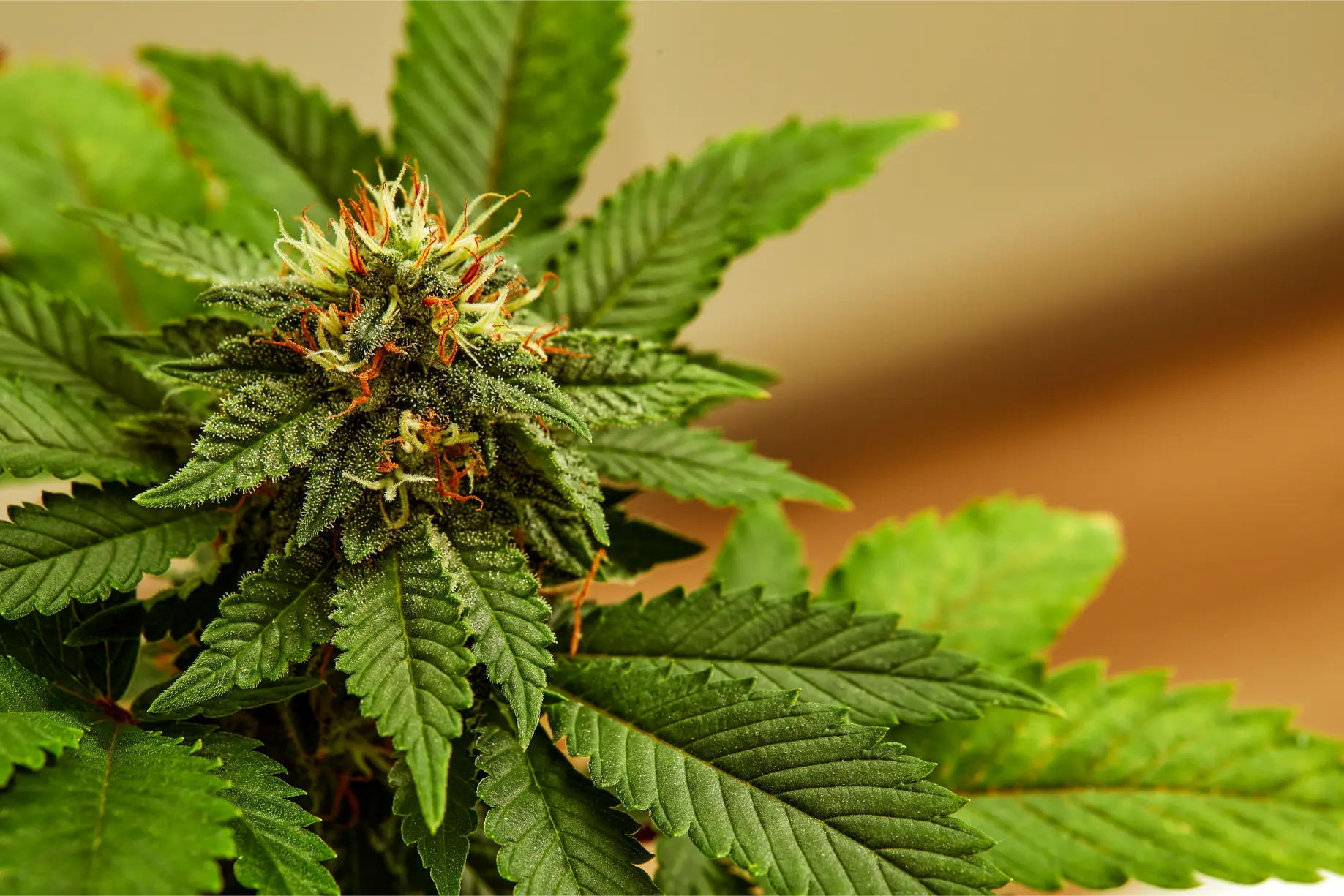
Figure 1: Robust foliar transpiration and stomatal conductance depend on rapid heat dissipation and uniform air exchange across the entire canopy profile.
Checkpoint 1.2: Inspect Carbon Filter Pre-Filter Loading. If mathematical thermal balance is confirmed but airflow remains sluggish, inspect the white polyester pre-filter sleeve wrapped around the activated carbon cylinder. In indoor grow rooms, atomized mineral dust from ultrasonic humidifiers running on tap water, airborne soil particulates, and aerosolized foliar sprays rapidly blind the outer pores of the pre-filter. A dust-caked pre-filter can increase system static pressure by 0.35 in. w.g., slashing fan throughput by more than 50 percent. Remove the pre-filter sleeve; if the fan immediately roars with increased airflow and tent temperature drops within fifteen minutes, wash the sleeve in warm water or replace it immediately.
Checkpoint 1.3: Audit Ducting Geometry, Bends, and Sagging. Examine the physical routing of flexible duct runs connecting the carbon filter, inline fan, and exhaust exit. Every 90-degree bend in flexible ducting introduces dynamic friction equivalent to adding 20 to 25 linear feet of straight duct run. S-curves, pinched elbows over tent roof poles, or unexpanded accordion ridges create severe boundary-layer separation and aerodynamic turbulence. Stretch all flexible foil ducting completely tight, eliminate unnecessary 90-degree elbows, and replace sharp flexible turns with rigid galvanized metal long-radius elbows to reclaim lost static pressure.
Checkpoint 1.4: Check for Air Short-Circuiting. Trace the path of exhausted air after it leaves the grow tent or room. If exhaust ducting discharges into the same room or hallway where the passive intake vent draws makeup air, an environmental short circuit is established. The exhaust fan expels hot air, which is immediately sucked back into the intake port, creating an escalating thermal loop that drives temperatures into severe crop-stalling territory.
Diagnostic Decision Branch 2: Severe Negative Pressure and Tent Wall Collapse
A properly ventilated grow tent should maintain a gentle inward bowing of its fabric walls, confirming that negative pressure is established to contain pungent terpene odors. However, when negative pressure becomes excessive, the fabric walls suck inward violently, collapsing the tent frame, bending vertical support poles, pinching the canopy perimeter, and threatening structural seam tearing. Follow this diagnostic sequence to resolve air starvation:
Checkpoint 2.1: Audit Intake-to-Exhaust Cross-Sectional Area Ratio. The fundamental engineering rule of passive horticultural ventilation states that passive intake vent area must be at least two to three times larger than the cross-sectional area of the active exhaust duct. For example, a 6-inch exhaust fan has a duct area of approximately 28.3 square inches. To feed that fan without creating severe suction resistance, total passive intake openings must provide at least 60 to 85 square inches of net free area. If the grower has only opened a single 6-inch lower vent port, the exhaust fan acts as a vacuum pump, starving the room of air and driving motor amp draw upward.
Mechanical Risk: Motor Cavitation and Fan Overheating
Running a high-velocity inline fan in an air-starved, high-vacuum tent creates severe aerodynamic turbulence across the impeller blades, known as fan stall or cavitation. Because air molecules cannot enter the housing fast enough to satisfy the low-pressure zone created by the spinning blades, air separates from the impeller surfaces, creating a loud buffeting acoustic rumble. Concurrently, because air density drops, convective cooling across the internal motor windings decreases, causing the motor casing temperature to climb rapidly.
Checkpoint 2.2: Inspect Passive Light Traps and Intake Insect Screens. Cultivators frequently install darkroom light baffles or fine mesh insect screens over lower intake vents to block stray light leaks and prevent pest ingress (such as fungus gnats, thrips, and spider mites). However, high-density insect screening and convoluted serpentine light traps introduce substantial air resistance. A standard 80-mesh pest screen cuts net free air area by up to 60 percent. If dust accumulates on these intake screens, the intake path becomes completely blocked. Vacuum intake screens weekly and increase total intake port area to compensate for screen resistance.
Checkpoint 2.3: Implement Active Intake Fan Interlocking. In sealed commercial grow rooms or expansive multi-tent setups where passive intake ports cannot provide sufficient airflow without light leakage, installing a dedicated active intake inline fan is required. However, active intake systems introduce a critical operational risk: if the intake blower runs faster than the exhaust blower, the space transitions into positive pressure, forcing unscrubbed cannabis terpenes through door frames, electrical outlets, and wall joints. Always configure active intake controllers to run at 15 to 25 percent lower CFM than the exhaust fan, guaranteeing constant negative pressure under all operating speeds.
My grow tent walls are sucking in so hard that the fabric is crushing my outer branches. How do I fix this without letting smell escape into my apartment?
Question sent by: Devon Harris, via email.
Violent tent wall collapse indicates severe air starvation caused by an undersized passive intake path. To fix this without risking odor leaks, you must increase your passive intake area while maintaining continuous negative pressure. Open additional lower mesh intake flaps or add an extra unpowered duct run fitted with a light-proof elbow trap; your total intake cross-sectional area should be two to three times larger than your exhaust duct diameter (for a 6-inch exhaust, you need at least two 6-inch intake ports or equivalent mesh area).
Additionally, install internal tent frame reinforcement bars (also called space-saver or high-CFM reinforcement kits). These rigid horizontal steel bars clip onto your vertical corner poles at mid-height, physically preventing the fabric walls from bowing inward against your plants. Finally, ensure your digital EC fan controller is programmed with smooth ramp speeds rather than abruptly jumping to 100 percent speed, allowing airflow to stabilize smoothly.
Frame reinforcement bars provide an immediate mechanical safeguard against tent fabric intrusion. By clipping horizontal bracing rods across the side walls at canopy height, growers maintain full interior growing volume while preserving the high static suction needed to ensure 100 percent odor containment.
Furthermore, growers should verify that lower passive intake vents draw clean, temperate air rather than stagnant floor air laden with spilled runoff or localized cold drafts. Positioning duct diffusers inside the intake ports helps distribute incoming fresh air uniformly beneath the plant canopy, preventing localized cold root zones while eliminating violent suction funnels.
Diagnostic Decision Branch 3: Odor Breakthrough and Filtration Breach
Odor control failure is the most urgent operational emergency in cannabis cultivation. When pungent monoterpenes and volatile sulfur compounds (VSCs) escape into living areas or ventilation exhaust outlets, immediate intervention is required. Execute this diagnostic branch to pinpoint the failure:
Checkpoint 3.1: Audit Exhaust Air Relative Humidity. The most common physical cause of sudden carbon filter breakthrough is excessive humidity. Virgin activated carbon utilizes millions of microscopic sub-nanometer pores to physically adsorb organic hydrocarbon molecules via Van der Waals forces. When relative humidity in the exhaust air stream rises above 70 percent (and especially above 80 percent), water vapor molecules condense into liquid droplets within the micropores, a phenomenon known as capillary condensation. The carbon bed becomes waterlogged, completely blinding the adsorption sites and allowing terpene molecules to pass through unscrubbed. Check exhaust air RH; if humidity is above 75 percent, activate supplemental dehumidification immediately.
The Physics of Adsorption: Critical Bed Contact Dwell Time
For activated carbon to capture volatile organic compounds effectively, air molecules must remain inside the packed carbon bed for a minimum contact duration termed dwell time. Horticultural carbon filters are engineered for a minimum dwell time of 0.10 to 0.15 seconds. If a cultivator connects an oversized 8-inch inline fan (moving 800 CFM) to a compact 6-inch carbon filter rated for only 400 CFM, air velocity through the carbon bed exceeds 100 feet per minute. Terpene molecules shoot through the carbon granules too quickly to be adsorbed, resulting in pungent odor breakthrough despite having a brand-new filter installed.
Checkpoint 3.2: Inspect Ductwork Seams Downstream of the Fan. Trace every seam, clamp, and joint in the ventilation duct run. If your carbon filter is mounted inside the tent and connects to the fan intake, the duct section between the filter and fan operates under negative pressure (suction). If a pinhole leak exists here, clean tent air is sucked into the duct, which does not leak smell. However, the ductwork downstream of the fan discharge operates under positive pressure. If a clamp is loose, or if thin single-ply foil ducting has suffered a tear from a sharp hose clamp, raw, unscrubbed air containing concentrated terpenes will be blown forcefully out into the room. Always secure duct connections with foil tape followed by heavy-duty stainless steel worm-gear clamps.
Checkpoint 3.3: Detect Carbon Bed Settling and Internal Channeling. Activated carbon filters subjected to mechanical vibration during shipping or long-term fan operation can experience granular carbon settling. If the cylindrical filter was hung horizontally without adequate support, carbon granules can settle toward the bottom of the cylinder, leaving an open air gap or void along the top internal perimeter. Air naturally bypasses the dense carbon bed and rushes through this path of zero resistance. Disconnect the filter, stand it vertically, gently tap the metal housing with a rubber mallet to redistribute granules, or replace the filter if it has exceeded its 12-to-18-month effective operational lifespan.
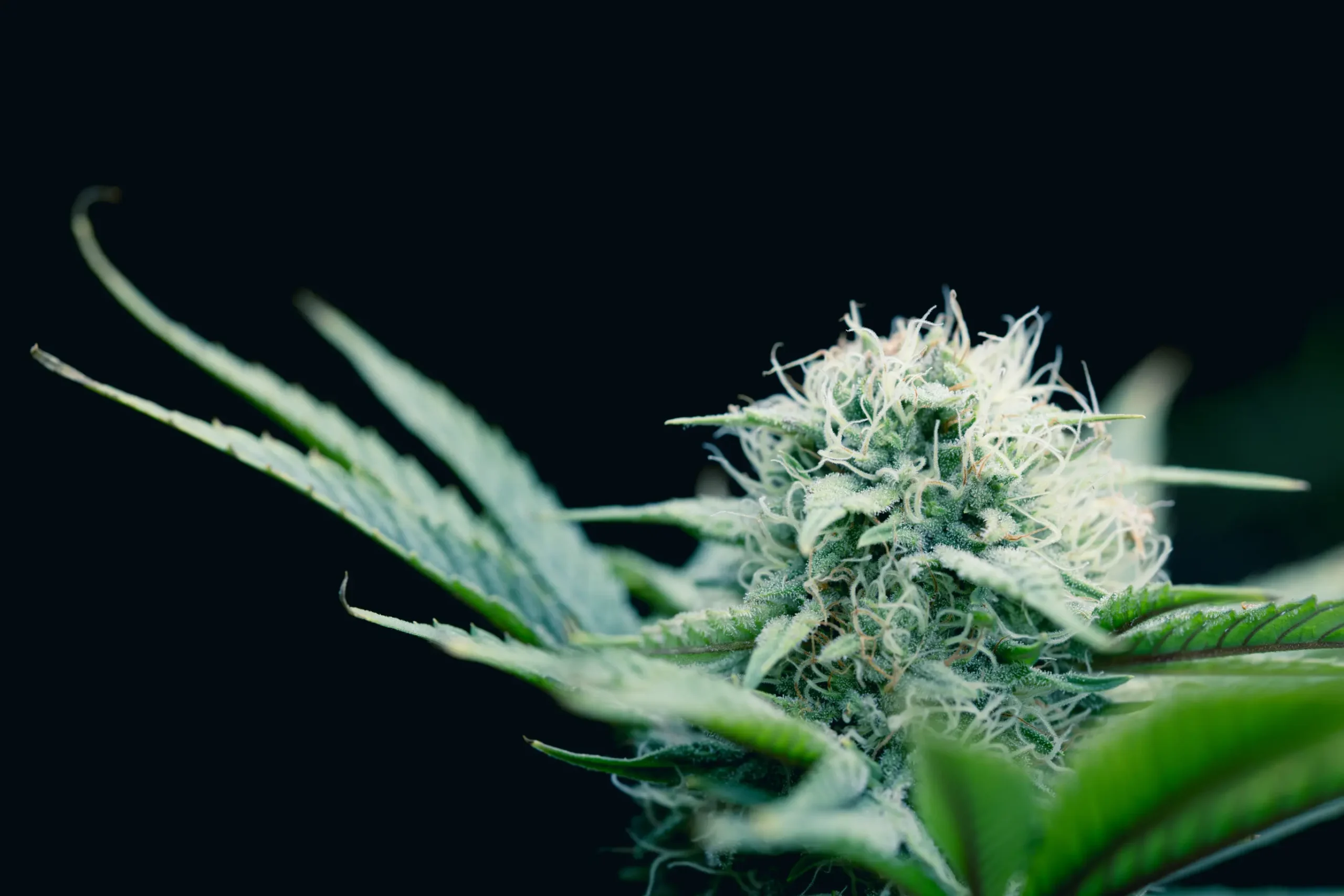
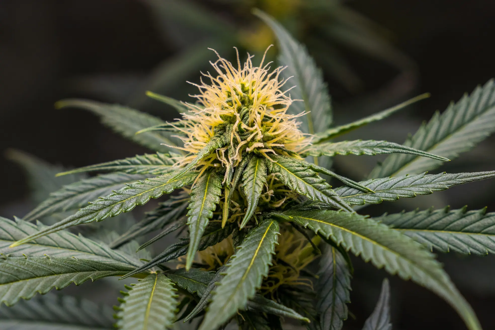
Figure 2: Peak flowering cultivars produce intense volatile terpene concentrations that demand flawless carbon filter contact dwell times and sealed duct joints.
Diagnostic Decision Branch 4: Ductwork Condensation and Internal Water Accumulation
Discovering water dripping from duct joints, pooling inside the volute housing of an inline fan, or leaking through exhaust louvers is a severe mechanical failure that risks electrical short circuits, ceiling water damage, and toxic mold blooms. Follow this psychrometric diagnostic branch:
Checkpoint 4.1: Compare Exhaust Dew Point to Ambient Attic/Duct Temperature. Air exhausted from a flourishing cannabis canopy during late flowering carries immense latent moisture, frequently measuring 24°C (75°F) at 60 percent RH. Consulting a psychrometric chart reveals that this air has a dew point temperature of approximately 15.6°C (60°F). If this warm, moisture-laden exhaust stream is routed through uninsulated flexible ducting traversing a cold attic, crawlspace, or exterior garage during winter where ambient temperatures are 5°C (41°F), the duct wall drops below the dew point. The warm air instantly sheds its vapor load, condensing into gallons of liquid water that flood the duct run.
Checkpoint 4.2: Replace Bare Foil Ducting with R-6 or R-8 Insulated Duct Sleeves. The physical correction for duct condensation is thermal decoupling. Replace all uninsulated bare aluminum flex ducting with double-walled insulated ducting featuring an R-6 or R-8 fiberglass or rockwool thermal blanket encased in a vapor barrier jacket. The insulation prevents the inner duct core from dropping below the exhaust air dew point, carrying moisture safely out of the building envelope before condensation can occur.
Checkpoint 4.3: Inspect Backdraft Dampers and Duct Slope Pitch. In cold climates, wind pressure can force frigid outdoor air backward through the exhaust termination hood when the fan runs at low speed. Install a spring-loaded, rubber-gasketed backdraft damper directly behind the exterior exhaust vent hood to block cold backdrafts permanently. Furthermore, ensure horizontal duct runs maintain a slight positive pitch (1/4-inch slope per foot) toward the exterior outlet, allowing any incidental droplets to drain outward rather than pooling backward into the fan motor assembly.
Critical Safety Hazard: Water Ingress into Electrical Motor Enclosures
Condensate accumulation inside exhaust ductwork poses an extreme electrical fire and shock hazard. If an inline fan is mounted vertically below an uninsulated vertical duct riser that exits through a cold roof deck, condensation running down the inner walls of the pipe will drip directly into the spinning motor bearings and electrical junction box. Always position inline fans horizontally or offset them using 45-degree elbows with dedicated condensate drain tees installed at the lowest elevation of the duct run.
Installing dedicated condensate traps or inline drain tees at low points in exterior ducting provides a fail-safe drainage route. By routing a small 1/4-inch vinyl drain line from a sealed drainage port down into a waste plumbing line or condensate collection reservoir, growers prevent liquid build-up from ever accumulating inside the ventilation core.
Additionally, growers operating in cold northern climates should schedule fan purge routines. Running the exhaust blower at moderate speed for fifteen minutes after lights-off helps flush lingering moisture from cold duct sections before night-time air stagnation permits water vapor to precipitate against chilled metal fittings.
Diagnostic Decision Branch 5: Controller Hunting, Speed Oscillations, and Sensor Bias
Modern automated climate controllers utilize digital sensors to modulate fan speeds dynamically. However, improper sensor installation or erroneous programming introduces severe operational instabilities. Follow this electronic troubleshooting branch:
Checkpoint 5.1: Eliminate Sensor Radiant Heat Bias. If your exhaust fan is constantly racing at maximum speed despite the room feeling cool to the touch, inspect the physical mounting location of your digital sensor probe. If the temperature sensor is suspended directly in the radiant cone of high-power LED bars or ceramic metal halide fixtures without a radiation shield, direct photon absorption heats the plastic probe body by 2°C to 5°C above true ambient air temperature. Mount the sensor inside a ventilated radiation shield or hang it directly beneath the canopy foliage in shaded, moving air.
Checkpoint 5.2: Widen Controller Hysteresis Deadbands. Controller hunting occurs when a digital speed controller rapidly ramps fan speed up and down every 30 to 60 seconds. This is caused by setting hysteresis buffer bands too tight (e.g., target temperature set to 25.0°C with a 0.2°C deadband). As soon as the fan speeds up, temperature drops 0.3°C and the controller throttles down; the moment the fan slows, temperature rises 0.3°C and the fan spikes again. Widen the temperature deadband to 1.5°C or 2.0°C and the relative humidity deadband to 5 percent. This gives the room atmospheric inertia to stabilize, eliminating annoying motor revving and mechanical wear.
Checkpoint 5.3: Check for High-Frequency Noise on 0-10V Signal Lines. In facilities utilizing 0-10V analog speed control cables, routing control wires parallel to high-current AC cords feeding electronic LED ballasts or air conditioning compressors induces high-frequency electrical noise onto the control wire. The fan’s microprocessor reads these phantom voltage spikes as fluctuating speed commands, causing erratic RPM jumping. Always use twisted-pair shielded control cables and maintain physical separation from high-voltage AC circuits.
Comprehensive Diagnostic Decision Tree Matrix
The following troubleshooting reference matrix synthesizes the five diagnostic branches into an immediate reference protocol for grow room operators.
| Primary Symptom | Root Physical Cause | Diagnostic Test / Measurement | Corrective Action |
|---|---|---|---|
| High Room Heat at 100% Fan RPM | Excess static pressure or warm intake air | Measure Delta-T between intake and exhaust; check pre-filter static pressure drop | Wash/replace dirty pre-filter sleeve; straighten duct bends; cool incoming lung room air |
| Tent Walls Crushing Inward | Severe air starvation (intake restriction) | Inspect passive intake area vs exhaust area; check insect screen dust buildup | Expand passive intake ports to 2-3x exhaust area; clean intake screens; install frame braces |
| Terpene Odor Breakthrough | High RH blinding carbon or excessive air velocity | Measure exhaust RH (>75%); calculate carbon filter dwell time (<0.1 sec) | Lower RH with dehumidification; down-regulate fan speed; verify duct joints downstream of fan |
| Water Dripping from Duct Joints | Exhaust air dew point higher than ambient duct temp | Measure attic temperature and compare against exhaust air dew point | Replace bare flex duct with R-6/R-8 insulated ducting; install spring-loaded backdraft damper |
| Fan Speed Surging Erratically | Narrow hysteresis or EMI on control cable | Review controller deadband settings; inspect 0-10V signal cable proximity to AC lines | Widen hysteresis deadband to ±1.5°C; shield low-voltage control cables; isolate from high-voltage runs |
By cross-referencing observed symptoms with this structured matrix, cultivators can immediately identify the underlying physical breakdown, apply targeted engineering corrections, and verify that atmospheric stability is fully restored.
Cultivators should retain a dedicated digital log of all ventilation parameter changes. Tracking static pressure baseline readings, seasonal humidity shifts, and carbon filter service dates ensures that maintenance schedules anticipate equipment wear before catastrophic environmental failure occurs.
Commissioning and Verification Sequence After Corrections
Whenever a mechanical, structural, or electronic correction is applied to an indoor grow room ventilation network, the cultivator must execute this four-step commissioning sequence before leaving the system to operate unattended.
- Step 1: The Incense/Smoke Negative Pressure Smoke Test. Power the ventilation system to its programmed minimum baseline speed (typically 15-20% capacity). Light a stick of incense or activate a theatrical smoke pen outside the closed zipper seams and passive vent openings. The smoke must be drawn cleanly and decisively inward toward the tent interior, confirming that positive pressure leaks are impossible.
- Step 2: Full-Speed Static Pressure and Amp Draw Verification. Switch the inline fan to 100 percent maximum speed. Measure operating current using a true-RMS clamp multimeter around the line conductor. The measured current must not exceed the maximum full-load amperage (FLA) indicated on the fan manufacturer nameplate, confirming the motor is not stalling under excessive static restriction.
- Step 3: Dual-Zone Psychrometric Enthalpy Audit. Deploy two calibrated digital hygrometers: one positioned directly inside the passive intake air stream, and one suspended inside the exhaust duct discharge. Verify that the exhaust stream is actively removing sensible heat and moisture without allowing exhaust duct wall temperatures to cross the calculated dew point threshold.
- Step 4: Fail-Safe Alarm and High-Temperature Cutoff Testing. Test automated safety systems by manually unplugging the primary environmental controller probe. Verify that the fan controller responds to probe disconnection by triggering an audible alert and defaulting the exhaust blower to 100 percent speed to prevent crop heat damage.
Executing this thorough commissioning verification ensures that newly installed ducts, replaced carbon filters, or reconfigured controllers perform reliably under commercial continuous-duty operating conditions.
Preventative Maintenance and Recheck Schedule
Adhering to a strict preventative maintenance schedule prevents unexpected ventilation breakdowns, preserves carbon filter longevity, and maintains optimal crop transpiration rates across every crop cycle.
| Service Interval | Target Component | Maintenance Action | Standard Operational Benchmark |
|---|---|---|---|
| Weekly | Intake Screens & Pre-Filters | Vacuum dust and debris from lower intake screens and filter outer sleeves. | Unrestricted intake velocity; zero visible lint or mineral buildup. |
| Monthly | Duct Clamps & Seams | Inspect all positive-pressure duct joints downstream of fan for loosening or tears. | 100% airtight seal; zero air leakage detected during hand-feel inspection. |
| Quarterly | Controller Sensor Probes | Clean sensor tip using clean compressed air; verify calibration against reference hygrometer. | Readings within ±0.5°C and ±3% RH of calibrated reference tool. |
| Every 2 Cycles (6 Mos) | Fan Impeller Blades | Disconnect power, open ducting, and clean resin/dust buildup off curved impeller blades. | Smooth aerodynamic rotation; zero mechanical vibration or acoustic flutter. |
| Annually (12-18 Mos) | Activated Carbon Bed | Conduct olfactory test at peak flowering; measure static pressure drop across cylinder. | Zero terpene breakthrough; replace cylinder when pressure rise exceeds 0.25 in. w.g. |
Following this structured schedule protects valuable crop investments, prevents costly emergency equipment replacements mid-bloom, and guarantees reliable, whisper-quiet ventilation performance season after season.
Scientific References and Technical Standards
- ANSI/AMCA Standard 201-16 (2016). Fans and Systems. Air Movement and Control Association International, Arlington Heights, IL.
- ASHRAE Handbook (2021). Fundamentals: Chapter 21 – Duct Design. American Society of Heating, Refrigerating and Air-Conditioning Engineers, Atlanta, GA.
- ASHRAE Handbook (2023). HVAC Applications: Chapter 24 – Controlled Environment Agriculture. ASHRAE, Atlanta, GA.
- Cooper, C. D., & Alley, F. C. (2011). Air Pollution Control: A Design Approach (4th ed.). Waveland Press, Long Grove, IL.
- Kramer, P. J., & Boyer, J. S. (1995). Water Relations of Plants and Soils. Academic Press, San Diego, CA.
- Taiz, L., Zeiger, E., Møller, I. M., & Murphy, A. (2015). Plant Physiology and Development (6th ed.). Sinauer Associates, Sunderland, MA.
Share this article
A quick overview of the topics covered in this article.
Follow us
Latest articles

November 6, 2026
November 6, 2026
November 6, 2026

November 6, 2026