Diagnosing Uneven Watering in an Indoor Grow
In high-efficiency controlled environment agriculture and precision commercial cannabis cultivation, irrigation uniformity is the foundational prerequisite for crop steering, nutritional consistency, and predictable harvest yields. In an optimized indoor garden, every plant across a cultivation table or room grid should transpire at a synchronized rate, absorb an identical volume of nutrient solution, and reach its target substrate dry-back threshold simultaneously. When irrigation delivery is uniform, environmental climate computers can execute precision vegetative or generative pulse feedings with absolute mathematical confidence.
In commercial reality, however, uneven watering is one of the most pervasive, silent destroyers of crop productivity. Cultivators frequently observe a room displaying severe canopy heterogeneity: plants near the front aisle are lush, dark green, and growing vigorously, while plants along the back wall appear stunted, pale, and water-stressed. In severe cases, half the containers in a room remain waterlogged and cold, while the other half are bone-dry and suffering from acute root-zone salt accumulation. Attempting to manage a divided room where some plants demand heavy irrigation while their neighbors are drowning creates an escalating management nightmare.
Diagnosing uneven watering requires looking beyond superficial foliar symptoms. Uneven moisture distribution is rarely an isolated mystery; it is the physical consequence of fluid dynamic imbalances within irrigation plumbing manifolds, mechanical clogging of micro-drip emitters, human operational bias during hand-watering, or structural substrate anomalies like hydrophobic bypass channeling. In this comprehensive technical guide, we dissect the hydraulic physics of fluid delivery, detail the industry-standard catch-can uniformity testing protocol, analyze diagnostic look-alikes, and establish proven engineering corrections to achieve 100 percent irrigation balance across your indoor canopy.
Mastering these hydraulic dynamics transforms commercial facility management from reactive firefighting into proactive engineering control. When every container in your facility receives an identical volume of water, plant canopies develop perfectly flat, uniform profiles that optimize photosynthetic light interception. Fertilizer input costs decrease significantly because growers no longer over-irrigate the entire room simply to satisfy a handful of dry, under-fed outlier plants along the bench margins.
The Engineering Standard: Christiansen’s Uniformity Coefficient (CU) and Emission Uniformity
In commercial agricultural engineering, irrigation distribution quality is measured by Christiansen’s Uniformity Coefficient (CU) and Emission Uniformity (EU). Formulated by irrigation engineer J.E. Christiansen, the coefficient mathematically quantifies the deviation of individual emitter discharge rates from the mean discharge across an entire irrigation block: CU = 100 x [1 – (Sigma |x_i – mean_x| / (n x mean_x))], where x_i represents individual emitter volume, mean_x is the average volume, and n is the total number of sampled emitters. In commercial controlled environment agriculture, an automated drip fertigation network must maintain an Emission Uniformity of at least 90 to 95 percent. An irrigation system operating with a CU below 80 percent guarantees chronic localized over- and under-watering that permanently suppresses facility profit margins.
To achieve high distribution uniformity, cultivators must recognize that fluid pressure inside an irrigation pipe is dynamic, not static. As nutrient solution travels through supply headers, friction against internal pipe walls, turbulent directional changes through elbow fittings, and continuous discharge from upstream drip stakes cause fluid pressure to decline progressively along the length of the pipe. If an irrigation manifold is improperly plumbed using non-pressure-compensating emitters, plants located close to the delivery pump receive high pressure and high volume, while plants at the terminal ends of the lines receive sluggish trickles.
Fluid movement through commercial irrigation pipe obeys the classic Darcy-Weisbach and Hazen-Williams hydraulic flow principles. As fluid velocity increases inside narrow distribution pipes, internal shear friction between the moving water and the polyethylene wall boundaries converts pressure head into mechanical heat loss. For example, forcing six gallons per minute through a standard half-inch polyethylene tube results in extreme friction loss exceeding fifteen feet of head per one hundred feet of pipe run. Consequently, a mainline operating at thirty pounds per square inch at the bench inlet can easily experience a steep pressure drop down to twelve pounds per square inch by the time water arrives at the terminal container row.
Furthermore, water temperature variations alter dynamic fluid viscosity. Cooler water delivered from subterranean nutrient tanks possesses higher kinematic viscosity than warm room-temperature solution, further amplifying laminar boundary layer friction inside micro-tubing. When supply lines run adjacent to high-intensity discharge ballasts or hot dehumidifier exhaust plumes, radiant heat elevates water temperature within localized pipe sections, causing significant density shifts that distort downstream delivery rates across identical emitters.
Hydraulic Selection: Non-Pressure-Compensating vs. Pressure-Compensating Emitters
Non-Pressure-Compensating (NPC) emitters discharge fluid through fixed internal orifices where volumetric output fluctuates directly with incoming line pressure. If friction causes line pressure to drop from 25 PSI at the pump to 10 PSI at the far bench end, NPC emitters will discharge up to 40 percent less water at the distal row. In contrast, commercial Pressure-Compensating (PC) emitters incorporate elastomeric silicone diaphragms that dynamically flex to constrict or expand internal discharge labyrinths. This mechanical compensation guarantees an identical, factory-calibrated flow rate (such as precisely 0.5 or 1.0 gallon per hour) across an operating pressure range of 10 to 45 PSI, neutralizing line friction loss entirely.
The operational difference between these two emitter technologies represents the single most common dividing line between amateur grow setups and professional commercial facilities. Cultivators who install budget micro-tubing assemblies without pressure regulation inevitably spend entire harvest cycles chasing ghost nutrient deficiencies. What appears to be an erratic nitrogen or potassium deficiency on terminal bench plants is almost universally chronic root desiccation caused by pressure-starved non-compensating drip stakes.
In addition to pressure compensation, precision emitters must incorporate internal elastomeric check valves, commonly designated as Non-Leakage (CNL) or Anti-Drain mechanisms. In standard open drip stakes, when the main fertigation pump cycles off, atmospheric pressure allows the fluid remaining within overhead supply pipes to drain via gravity into the lowest physical pots on the table. This siphon drainage can dump hundreds of milliliters of unintended runoff into low-lying containers after every single pulse event, keeping their root systems permanently hypoxic while elevated containers receive only their calibrated volumetric ration.
Anti-drain emitters prevent this devastating drainage error by snapping tightly shut the millisecond line pressure drops below seven to ten pounds per square inch. By holding the distribution pipe fully charged with fluid between irrigation cycles, CNL emitters ensure instantaneous, simultaneous discharge across all hundred or thousand plants the instant the fertigation pump energizes. Without anti-drain check valves, the first thirty to sixty seconds of every irrigation pulse are wasted merely refilling empty supply headers, creating severe time-lag variations across distant bench quadrants. Furthermore, commercial facilities install pressure gauges at both the manifold inlet and terminal end-points. Monitoring the differential pressure across the manifold allows technicians to instantly identify developing line restrictions, biological clogging, or pump degradation before crop transpiration is compromised.
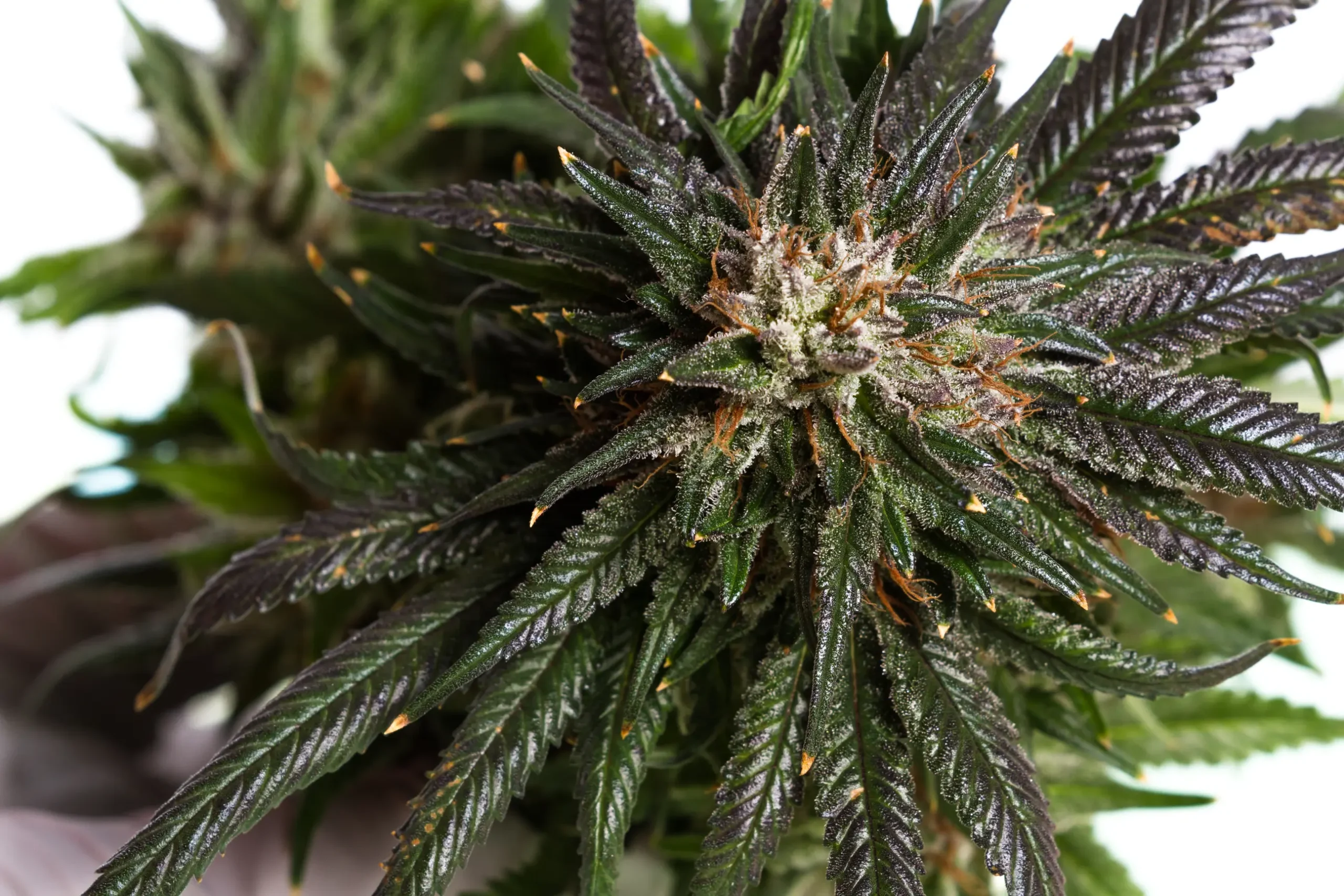
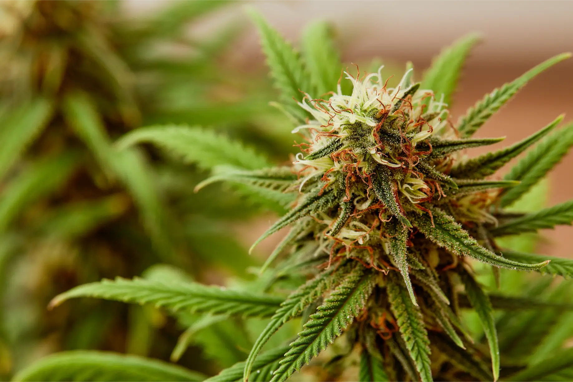
Figure 1: High emission uniformity across automated drip manifolds ensures synchronized flowering onset and even calyx maturation.
Beyond manifold friction and elevation siphonage, mechanical clogging represents the primary operational threat to emitter discharge uniformity. Concentrated mineral salts in cannabis fertigation recipes (most notably calcium phosphate, calcium sulfate, and magnesium carbonate) continually precipitate along the microscopic pathways of emitter tortuous paths. As dissolved solids exceed saturation thresholds due to localized evaporation or temperature swings, crystalline scale accumulates along plastic walls, choking water passage without causing complete cessation of flow.
Simultaneously, biological contaminants exploit nutrient-rich irrigation headers. Autotrophic bacteria, micro-algae, and fungal spores form slippery biofilms along internal pipe surfaces, especially when organic root stimulators, fulvic fractions, or amino-acid-chelated micronutrients are introduced into reservoirs. These biological polymers slough off in microscopic sheets, lodging in drip stake orifices and creating erratic flow restrictions that vary wildly from pot to pot. A partially occluded stake delivering seventy percent of calibrated flow will quietly starve a plant for weeks before visible wilting prompts manual investigation.
Substrate physical dynamics further distort water distribution across containers. In peat-based potting soils and coconut coir blends, structural pore size distribution dictates capillary matric suction. If a batch of potting medium is packed into nursery containers with inconsistent manual compaction, adjacent pots will exhibit radically different bulk densities. A container packed with firm hand pressure possesses smaller micropores that hold water tightly against gravitational drainage, whereas an adjacent pot filled loosely with dry, airy media contains expansive macropores that drain instantly, drying out in half the time.
The Saucer Re-Wicking Hazard: Why Flat Pots Stay Saturated
Allowing plant containers to sit flat on the floor of drainage trays creates localized waterlogging that masquerades as an irrigation problem. When excess drainage runoff collects in a flat plastic saucer, containers that sit directly in standing water reabsorb that effluent through their bottom drainage holes via capillary wicking. Through this reverse wicking process, the bottom third of the container remains permanently 100 percent saturated, while an adjacent container elevated on a pot riser drains freely into the air. Always install rigid pot elevators or wire grids beneath every container to break capillary contact with standing drainage wastewater.
Even more insidious is preferential bypass channeling caused by hydrophobic substrate shrinkage. Peat moss and coconut coir fibers are inherently prone to hydrophobicity when dried below critical volumetric moisture thresholds. When moisture drops below twenty percent, organic waxes on fiber surfaces repel water molecules, forcing applied fertigation liquid to take the path of least physical resistance.
As the soil mass dries and contracts, it pulls inward away from the smooth plastic container walls, establishing an open annular void around the root ball. During subsequent top-feeding events, irrigation water races down this outer perimeter crevice and drains out the container base in seconds. The cultivator observes abundant drainage runoff and assumes the root zone has been thoroughly saturated, when in biological fact ninety percent of the internal root core remains bone-dry. Measuring container mass before and immediately after irrigation is the only reliable diagnostic method to unmask bypass channeling.
Human operational bias also contributes heavily to uneven moisture profiles in hand-watered gardens. Ergonomic studies in commercial greenhouses prove that human workers systematically deliver between twenty and thirty-five percent more liquid volume to containers situated along primary walking aisles where posture is comfortable and reach is unobstructed. Conversely, plants located in deep bench corners, beneath support trellis netting, or near hot electrical equipment receive hurried, inadequate watering, creating a predictable geographic moisture gradient across the facility.
Why are the plants at the far end of my drip line smaller and lighter than the plants close to my water pump?
Question sent by: Trevor Sinclair, via email.
The stunted growth and light container weights at the far end of your drip line indicate severe hydraulic friction head loss combined with non-pressure-compensating emitters. As nutrient solution travels down your distribution pipe, friction against the pipe walls causes fluid pressure to drop progressively. Emitters near your pump are receiving 25 PSI and discharging their full rated volume, while emitters forty feet down the line are receiving only 8 to 10 PSI, discharging 30 to 50 percent less water during every scheduled pulse!
To fix this permanently, you should implement two engineering upgrades: (1) Upgrade all drip stakes to true Pressure-Compensating (PC) emitters (such as Netafim PC stakes), which maintain an identical, factory-calibrated flow rate (e.g., exactly 0.5 GPH) regardless of line pressure fluctuations between 10 and 45 PSI; and (2) Loop your irrigation manifold: connect the dead end of your drip line back into the main supply header or increase your main pipe diameter from 1/2-inch to 3/4-inch to eliminate pressure drops across the length of the table.
Executing an objective diagnostic evaluation requires eliminating subjective observation in favor of empirical volumetric data. The gold standard methodology for evaluating indoor fertigation performance is the Catch-Can Distribution Uniformity Audit. This protocol isolates mechanical plumbing performance from environmental microclimates, establishing precisely how evenly liquid is being delivered to each root zone.
To perform an audit, technicians deploy graduated collection cylinders or uniform plastic cups beneath a representative matrix of drip emitters across the room. In a standard bench setup, sample at least sixteen distinct points: four emitters adjacent to the pump header inlet, four along the center spine, four at the distal line terminations, and four along outer lateral branches. Ensuring identical container placement beneath each stake prevents splashing and collection losses during high-velocity discharge pulses.
Once collection vessels are securely positioned, initiate an automated irrigation pulse through your master climate or irrigation controller. Run the delivery pump for a precisely timed interval, typically three to five minutes, or the exact duration of a standard operational shot. Allow all residual dripping to conclude completely after pump de-energization, ensuring that low-elevation drainage phenomena are captured in the total volumetric tally.
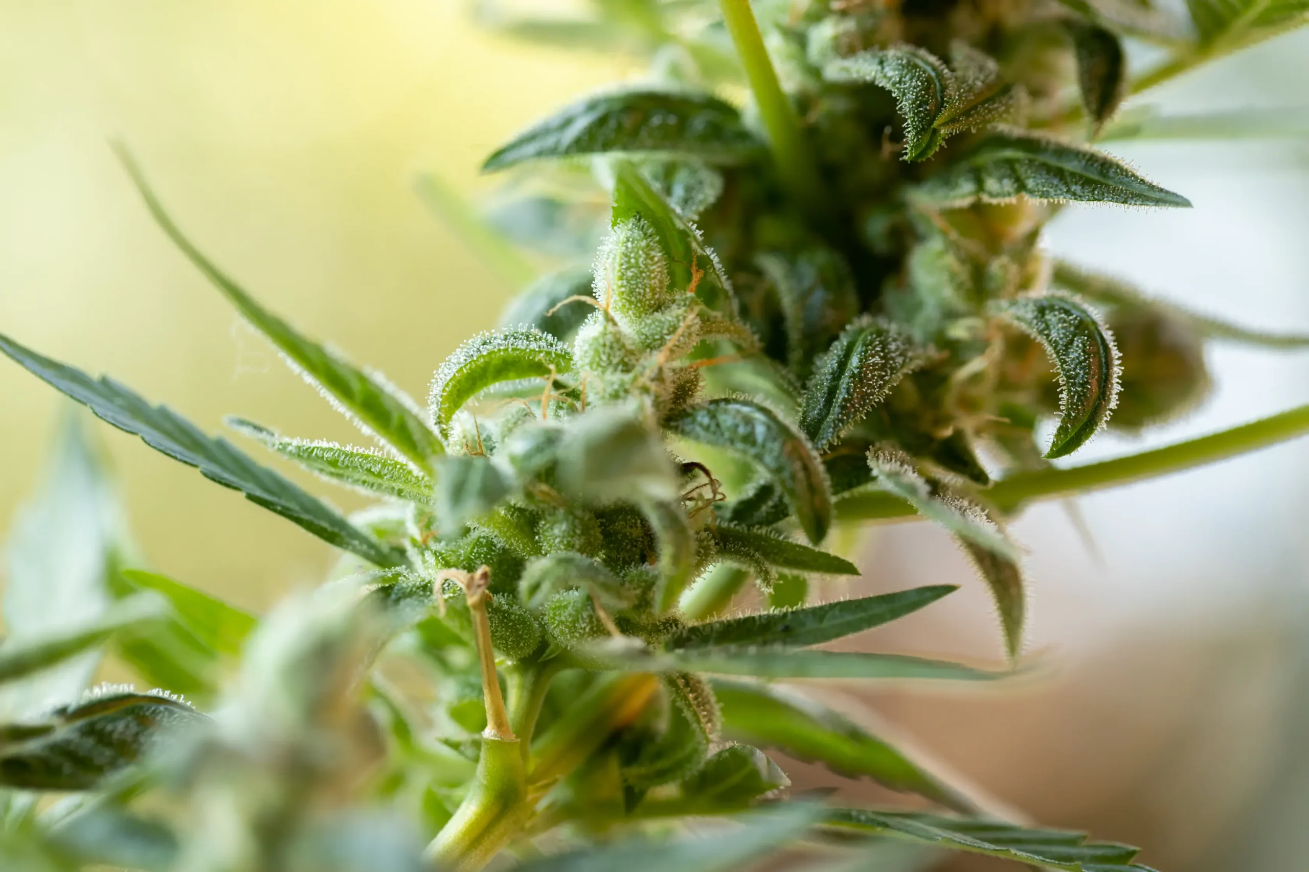
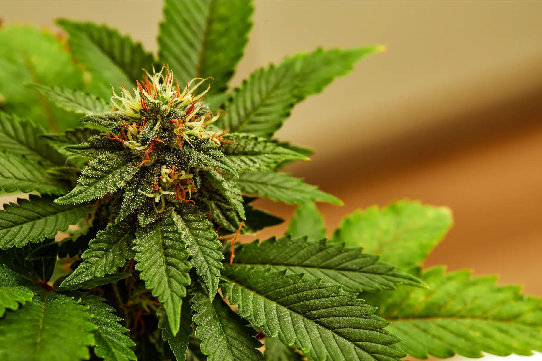
Figure 2: Consistent vegetative growth rates and uniform stomatal aperture depend on equalized volumetric water delivery across every container in the room.
After collection concludes, measure and record the liquid volume in milliliters from each container using a high-accuracy laboratory graduated cylinder. Calculate the average discharge volume across all sampled emitters, then calculate both the Christiansen Uniformity Coefficient (CU) and the Low-Quarter Distribution Uniformity (DU_lq). Low-quarter uniformity specifically evaluates the average volume of the lowest twenty-five percent of emitters divided by the overall mean volume, providing immediate insight into whether a localized subgroup of plants is being systematically starved.
A calculated DU_lq value exceeding eighty-eight percent indicates excellent commercial distribution uniformity. If your measured uniformity falls between seventy-five and eighty-five percent, manifold pressure drops, minor line sediment, or mixed emitter ages are degrading performance and require operational remediation. A score below seventy-five percent represents an acute mechanical failure demanding immediate structural re-engineering of the distribution plumbing.
When analyzing uneven watering symptoms, cultivators must also differentiate mechanical delivery failures from environmental look-alikes. For instance, localized microclimate hotspots beneath non-uniform LED lighting arrays can double plant transpirational demand in specific canopy zones. A plant situated under 1,000 micromoles per square meter per second of photosynthetic photon flux density will deplete root-zone moisture twice as fast as an identical plant receiving 500 micromoles along the bench margin, even when both receive identical irrigation volumes. Similarly, high-velocity air currents from poorly aimed oscillating fans dramatically accelerate boundary layer vapor pressure deficit, accelerating substrate dry-down without any underlying plumbing flaw.
| Diagnostic Observation | Mechanical Emitter Clog | Substrate Bypass Channeling | Uneven Hand-Watering Bias | Localized Airflow Hotspot |
|---|---|---|---|---|
| Catch-Can Emitter Volume | Abnormally Low (-30% to -80%) | Normal calibrated delivery | N/A (Hand-poured disparity) | Normal calibrated delivery |
| Pot Weight 10 Min Post-Watering | Very Light (Never received water) | Light (-30% of normal full weight) | Disparate across room grid | Heavy (Normal full weight) |
| Runoff Volume at Irrigation | Zero runoff produced | Excessive instant runoff (>50%) | Variable (Front high, back low) | Normal (10-15% delayed runoff) |
| Dry-Down Velocity | Appears dry immediately | Appears dry in 12-24 hours | Inconsistent across benches | Fast (Transpires in 24-36 hrs) |
| Definitive Remediation | Replace / acid-flush emitter | Bottom-soak with yucca surfactant | Deploy metered hand wands | Re-aim fans; rotate pot position |
Resolving mechanical delivery imbalances permanently requires correcting the hydraulic geometry of your distribution plumbing. The most potent engineering intervention for eliminating manifold pressure drop is converting linear dead-end headers into closed-loop ring manifolds. In a traditional linear layout, fluid enters one end of a pipe and terminates at a sealed end-cap, creating an inescapable pressure gradient along its length. In a closed-loop ring circuit, supply water enters the manifold through a balanced center tee, splits in both directions around the perimeter of the cultivation bench, and reconverges at the far side.
Looping the distribution header equalizes hydrostatic pressure across every square inch of the table. Water reaches distal branch lines from two simultaneous directions, cutting effective flow distance in half and slashing line friction loss by up to seventy-five percent. When coupled with an upgrade to three-quarter-inch or one-inch commercial schedule-40 PVC or thick-walled polyethylene tubing, pressure drop across forty-foot rolling benches becomes virtually unmeasurable.
Additionally, maintaining fluid scouring velocity is critical for preventing mineral sedimentation and biofilm adhesion inside header pipes. Irrigation engineers recommend sizing mainlines to maintain a minimum internal fluid velocity of 1.5 to 2.0 feet per second during active pumping cycles. High scouring velocity prevents suspended solids from settling along pipe inverts, carrying fine particulates safely toward terminal cleanout valves rather than allowing them to choke lateral micro-tubes. When header pipes are oversized excessively, such as using a 2-inch pipe for a modest 5-GPM flow rate, fluid velocity drops below critical settling thresholds, allowing silt, calcium flakes, and organic matter to precipitate into stagnant boundary layers along pipe inverts.
Maintenance Engineering: Periodic Acid Flushing for Mineral Descaling
Over months of continuous fertigation, concentrated calcium, magnesium, and phosphate salts precipitate within the tortuous microscopic labyrinths of drip emitters, gradually restricting flow. Commercial facilities maintain emission uniformity by executing periodic line descaling between cycles (or during vegetative resets). Inject a 5 percent food-grade Citric Acid solution or commercial agricultural line cleaner (such as Athena Reset or sulfuric-based acid descalers) into the delivery manifold. Allow the acid solution to dwell inside the pressurized lines for four to six hours to dissolve crystalline mineral scale completely, then flush with fresh RO water before replanting.
Beyond chemical descaling, mechanical filtration serves as your primary line of defense against emitter degradation. Every commercial fertigation skid must incorporate heavy-duty depth filtration directly downstream of the pressure pump. While simple mesh screen filters capture large flakes of plastic shavings or reservoir debris, they allow elongated organic fibers and pliable fungal mycelium to squeeze through openings under hydraulic pressure.
In contrast, commercial grooved disc filters force irrigation water to navigate hundreds of microscopic, compressed plastic disc rings etched with diagonal grooves. This creates an intricate three-dimensional filtration maze that captures both hard mineral particles and soft biological colloids down to 130 microns (120 mesh) without premature surface blinding. Installing dual parallel disc filters allows operators to manually isolate and backwash one filter assembly during operation without interrupting automated pulse schedules.
For operations relying on manual hand-watering, the definitive cure for human operational bias is deploying digital flow-metering wands. These industrial delivery wands integrate precision turbine flow sensors connected to digital liquid crystal displays directly on the ergonomic handle. Rather than counting seconds or guessing container weight, technicians press a trigger to dispense a mathematically calibrated volume (such as exactly 1.75 liters) into each container before the integrated shutoff valve closes. This transforms subjective hand-watering into an auditable, repeatable industrial procedure.
- Closed-Loop Manifold Plumbing Confirmed: Verify that drip supply headers are plumbed as closed-loop rings or oversized 3/4-inch to 1-inch lines to eliminate pressure drop across benches.
- Pressure-Compensating Emitters Installed: Ensure all drip stakes are certified pressure-compensating (PC) models equipped with anti-drain (CNL) check valves to prevent siphon drainage.
- Catch-Can Uniformity Audit Executed: Conduct a 16-point catch-can test; verify Christiansen’s Uniformity Coefficient (CU) exceeds 90 percent across the entire room.
- Inline 100-Mesh Disc Filter Cleaned: Inspect, disassemble, and clean the primary disc filter downstream of the delivery pump; confirm zero sediment bypass.
- Line Pressure Gauge Installed: Install a liquid-filled pressure gauge at the terminal end of the distribution manifold to monitor line operating pressure (target 20 to 30 PSI).
- Elevated Pot Risers Positioned: Confirm that every plant container sits elevated upon a rigid plastic elevator, guaranteeing an unbroken air gap above drainage saucers.
Transitioning from mechanical commissioning to full vegetative growth requires continuous validation of substrate volumetric moisture content. While catch-can audits verify that emitters deliver identical water volumes to the surface of the container, electronic substrate sensors confirm whether that water is dispersing uniformly through the root core. Inserting time-domain reflectometry (TDR) or frequency-domain capacitance probes into multiple containers across diverse bench zones provides real-time data on dry-down trajectories.
If continuous telemetry reveals that a specific corner of the bench consistently dries out two hours faster than the room average, cultivators can immediately investigate microclimatic drivers such as localized HVAC airflow currents, supplemental dehumidifier draft paths, or high-intensity LED driver radiation. Precision crop steering relies entirely on eliminating these micro-environmental discrepancies, enabling growers to push aggressive dry-backs during generative bud development without pushing outlier plants into fatal wilting or severe osmotic shock.
Furthermore, establishing automated electrical conductivity (EC) monitoring of collection runoff allows facility managers to detect early-stage root-zone divergence. When an individual container receives fifteen percent less irrigation volume than its neighbors over several consecutive days, residual mineral salts are not adequately leached. The electrical conductivity inside that root ball will escalate rapidly from 2.5 mS/cm up to 6.0 mS/cm or higher, creating acute osmotic stress that shuts down vegetative expansion long before physical leaf symptoms manifest.
| Maintenance Interval | Target Component | Inspection and Service Action | Operational Benchmark |
|---|---|---|---|
| Daily | Canopy Dry-Back Uniformity | Visually inspect canopy turgor and lift test representative containers across all bench zones. | Containers dry back at synchronized rates; zero outlier flaccid or heavy pots. |
| Weekly | Drip Line Terminal Flush | Open manual flush valves at the ends of all drip lines for 15 seconds under full pump pressure. | Flushes settled sediment and biological biofilms; clear effluent discharged. |
| Weekly | Primary Disc Filter Screen | Isolate main valve, unscrew filter housing, remove grooved disc cartridge, rinse clean under tap. | 100% unobstructed filter rings; zero pressure drop across filter body. |
| Monthly | Catch-Can Uniformity Spot Check | Place graduated cylinders under eight random emitters across the room; run a 3-minute pulse. | Discharge variation within ±5% of mean; zero partially clogged emitters. |
| Between Cycles | Full-System Acid Descaling | Circulate 5% food-grade citric acid solution through all lines and stakes for 4 hours; flush with RO. | Completely dissolves mineral salt scale; restores 100% factory flow rates. |
| Between Cycles | Micro-Tubing Replacement | Inspect flexible 1/8″ and 1/4″ micro-tubing; replace any cracked, pinched, or brittle lines. | Pliable, clean distribution tubing; zero weeping connection fittings. |
Institutionalizing a preventative maintenance culture ensures that mechanical irrigation infrastructure delivers flawless performance across years of continuous indoor crop production. Cultivators who systematically verify delivery uniformity protect their high-value crops against the insidious financial losses caused by uneven canopy maturation, erratic cannabinoid synthesis, and inconsistent dry flower yields.
Long-term operational success requires tracking baseline irrigation metrics across multiple crop cycles. Facility logs should record operating pressure at both the pump discharge and manifold terminations, ensuring that pump impeller wear or line sediment does not quietly erode delivery pressure over time. When irrigation pumps age, their head curves degrade, reducing flow rates and leaving distal emitters operating near the absolute lower boundary of their pressure-compensation range.
By combining closed-loop manifold engineering, certified pressure-compensating emitters, robust depth disc filtration, and periodic catch-can audits, indoor cultivators achieve true industrial mastery over their fertigation environment. In precision controlled environment cannabis production, irrigation uniformity is not merely an aesthetic convenience; it is the ultimate foundation upon which commercial yield, potency, and profitability are built.
Scientific References and Technical Standards
- ASABE Standards (2017). ANSI/ASAE S398.1: Procedure for Sprinkler Testing and Performance Reporting. American Society of Agricultural and Biological Engineers, St. Joseph, MI.
- Burt, C. M., Clemmens, A. J., Strelkoff, T. S., Solomon, K. H., Bliesner, R. D., Hardy, L. A., Howell, T. A., & Eisenhauer, D. E. (1997). Irrigation performance measures: Efficiency and uniformity. Journal of Irrigation and Drainage Engineering, 123(6), 423-442.
- Christiansen, J. E. (1942). Irrigation by Sprinkling (California Agricultural Experiment Station Bulletin 670). University of California, Berkeley, CA.
- Handreck, K. A., & Black, N. D. (2002). Growing Media for Ornamental Plants and Turf (3rd ed.). UNSW Press, Sydney, Australia.
- Keller, J., & Bliesner, R. D. (1990). Sprinkle and Trickle Irrigation. Van Nostrand Reinhold, New York.
- Taiz, L., Zeiger, E., Møller, I. M., & Murphy, A. (2015). Plant Physiology and Development (6th ed.). Sinauer Associates, Sunderland, MA.
- Zheng, Y. (Ed.). (2021). Handbook of Cannabis Production in Controlled Environments. CRC Press, Boca Raton, FL.
Share this article
A quick overview of the topics covered in this article.
Follow us
Latest articles
November 6, 2026

November 6, 2026

November 6, 2026
November 6, 2026