HVACD for Indoor Cannabis: Sensible and Latent Loads Explained
In modern commercial cannabis cultivation, environmental control has evolved far beyond traditional residential air conditioning. Standard commercial comfort-cooling HVAC systems are engineered to manage spaces where 70 to 80 percent of the total thermal load is dry, sensible heat generated by outdoor solar gain, building conduction, and human occupants, with only 20 to 30 percent representing latent moisture. Installing standard comfort-cooling air conditioning inside an indoor cannabis flower room is an engineering failure. An intensive botanical grow room operates under an inverted thermodynamic profile: up to 50 to 60 percent of the total cooling load consists of latent transpirational moisture released by the plant canopy.
This fundamental thermodynamic divergence gave birth to the specialized engineering discipline of HVACD: Heating, Ventilation, Air Conditioning, and Dehumidification. In high-performance controlled environment agriculture (CEA), heating, cooling, and moisture removal cannot be treated as separate, competing mechanical processes. When independent air conditioners, residential portable dehumidifiers, and exhaust fans battle each other for thermal dominance, the result is extreme temperature swings, erratic vapor pressure deficit (VPD), massive electrical utility waste, and rapid mechanical failure. True environmental stability requires an integrated psychrometric design that balances sensible heat removal and latent moisture extraction simultaneously.
Thermodynamic Law: Sensible vs Latent Heat and the Sensible Heat Ratio
The total heat load (Enthalpy) of an indoor cultivation room is divided into two distinct components: Sensible Heat, which directly changes air temperature without changing moisture content, and Latent Heat, which is the thermal energy bound within airborne water vapor during the phase change from liquid to gas. The proportion between these two forces is defined by the Sensible Heat Ratio (SHR): Sensible Heat divided by Total Heat (Sensible plus Latent). While a standard office building operates at an SHR of 0.80 to 0.85, a sealed cannabis flower room during peak photoperiod operates at an SHR between 0.45 and 0.55.
Operating at an SHR near 0.50 means that for every BTU of dry sensible heat produced by LED lighting fixtures, electrical ballasts, and fan motors, the air conditioning and dehumidification equipment must remove an equivalent BTU of latent heat stored in transpirational water vapor. Standard air conditioners are mechanically incapable of operating at this low sensible heat ratio. When a standard AC cooling coil drops room temperature to the thermostat setpoint, its compressor shuts off, completely halting moisture removal even though relative humidity remains dangerously elevated.
To overcome this limitation, specialized horticultural HVACD systems incorporate active reheat coils (utilizing hot compressor discharge gas or modulating hydronic loops) and dedicated variable-speed compressors. By chilling the air below its dew point across a cold evaporator coil to condense water vapor, and then immediately reheating that cold, saturated air before re-injecting it into the room, an integrated HVACD system extracts immense volumes of latent moisture without overcooling the cultivation space.
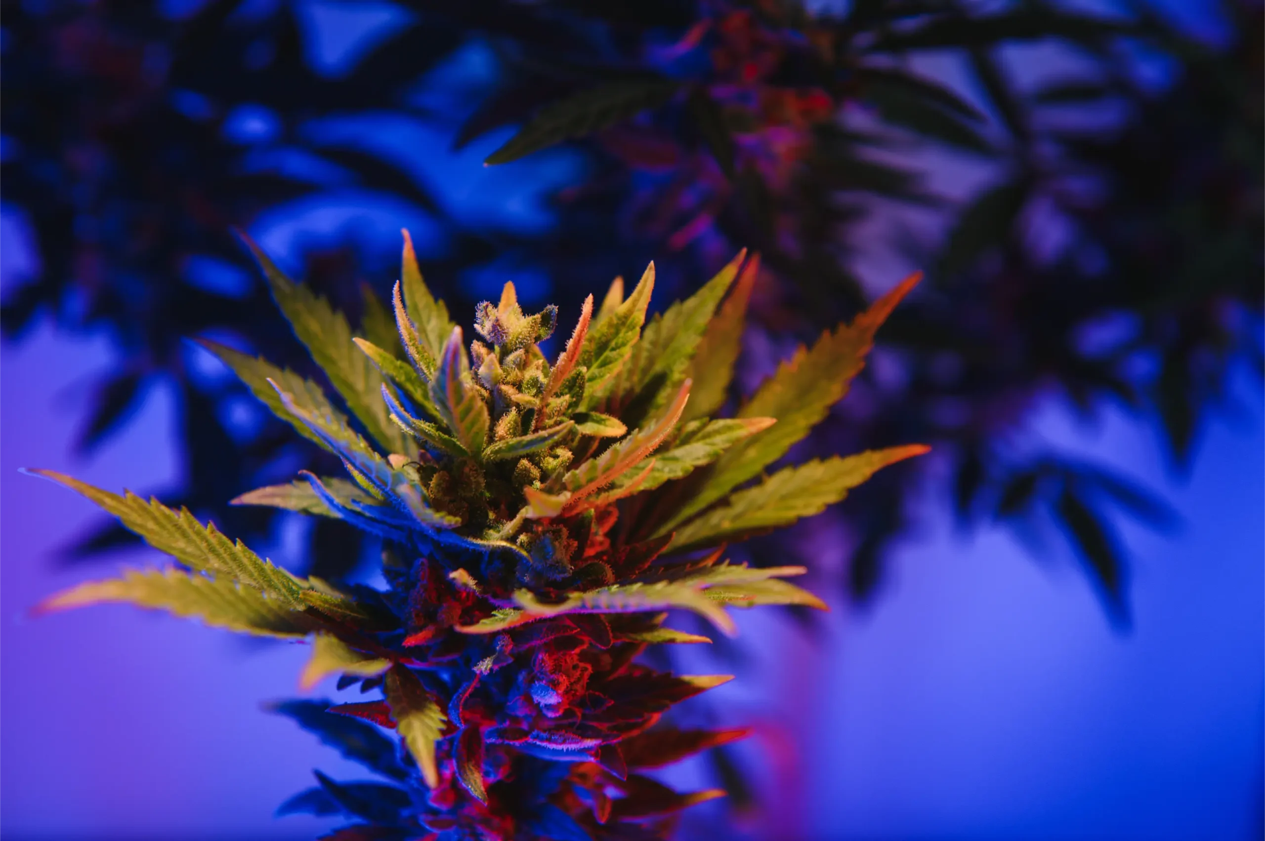
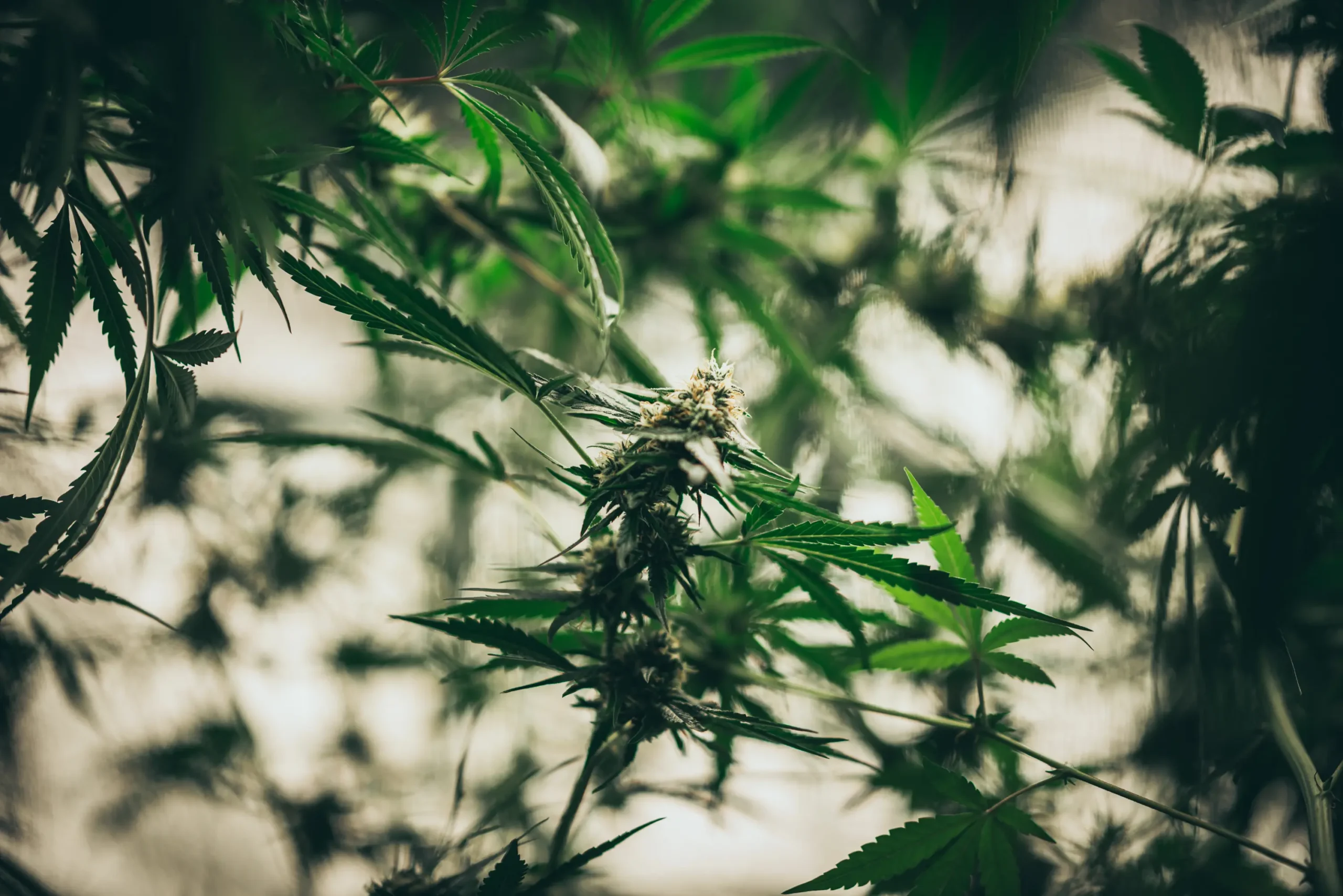
High-intensity LED spectral lighting generating dry sensible heat, while underlying crop canopy converts irrigation into massive latent transpirational moisture loads.
The conversion of sensible lighting energy into latent moisture is a direct biological process driven by foliar transpiration. When photons hit cannabis leaves, only 3 to 5 percent of that electromagnetic radiation is captured biochemically through photosynthesis. The remaining 95 percent of absorbed photonic energy is converted into heat. To prevent foliar tissue from scorching under intense illumination, plants open their stomatal guard cells and evaporate liquid water into the surrounding air. In doing so, the crop converts dry sensible heat into airborne latent heat at a rate of approximately 1,061 BTU per pound of evaporated water.
Consequently, lighting wattage and irrigation volume are thermodynamically linked. You cannot design an HVACD system by looking at light wattage alone, nor can you size dehumidification without calculating irrigation volume. Mastering the biophysical interplay between sensible and latent loads is the foundation upon which commercial facility reliability, energy efficiency, and crop health are built.
Defining the Controlling Airflow, Psychrometric, and Thermodynamic Variables
Designing an effective HVACD system requires defining the exact physical variables that govern indoor atmospheric dynamics. These variables include volumetric airflow (CFM), external static pressure (ESP in water gauge inches), dry-bulb temperature (degrees Celsius), relative humidity (RH percentage), dew point temperature (degrees Celsius), humidity ratio (grains of moisture per pound of dry air), and Leaf Vapor Pressure Deficit (Leaf VPD in kilopascals).
A frequent error in commercial facility design is treating relative humidity as an isolated metric. Relative humidity is a moving target that fluctuates inversely with temperature. In contrast, dew point and humidity ratio are absolute physical measurements of moisture mass in the air. For example, air at 26 degrees Celsius and 60 percent RH holds approximately 89 grains of moisture per pound of dry air, with a dew point of 17.6 degrees Celsius. If that same air cools to 20 degrees Celsius without removing a single drop of water, its relative humidity automatically surges to 86 percent, and the dew point remains at 17.6 degrees Celsius.
We installed a 10-ton commercial rooftop air conditioner in our 30-light flower room. During the day, the temperature stays locked at 24 degrees Celsius, but the humidity hovers at 72%. Why isn’t our 10-ton AC removing the moisture?
Your 10-ton air conditioner is short-cycling because it satisfies the sensible temperature setpoint too quickly, leaving insufficient runtime to extract latent moisture. Comfort-cooling AC coils have a high Sensible Heat Ratio (around 0.75 to 0.80); they are designed to cool air rapidly, not dehumidify heavily. Once the room hits 24 degrees Celsius, the thermostat shuts the compressor off, stopping condensation. To fix this, you must install dedicated commercial dehumidifiers to handle the latent transpirational load or integrate modulating hot-gas reheat into your air handling system.
Question sent by: Soren, via email.
Soren’s challenge illustrates the classic failure mode of comfort-cooling equipment applied to indoor horticulture. When oversized cooling equipment satisfies the thermostat in short 5-minute bursts, the evaporator coil never remains cold long enough to establish continuous condensation. Moisture that briefly condensed on the aluminum coil fins during the cooling cycle does not have time to drain away; instead, when the compressor shuts off and the supply fan continues running, that standing water evaporates right back into the supply air stream, driving humidity spikes.
In contrast, purpose-built horticultural HVACD systems modulate compressor displacement using variable-speed inverter technology or digital scrolls. By modulating capacity to match real-time sensible loads, the evaporator coil remains continuously chilled just above freezing, stripping latent water vapor non-stop while hot-gas reheat coils warm the supply air back to the exact target dry-bulb setpoint.
System Layout: Supply Ducting, Return Paths, Static Pressure, and Sensor Geometry
The physical geometry of supply and return ductwork dictates whether conditioned air reaches the plant canopy uniformly or creates destructive microclimates. Air is a viscous fluid that follows the path of least aerodynamic resistance. If ductwork is poorly engineered, supply air short-circuits directly into return grilles, leaving the plant canopy suffocating in stagnant heat and humidity.
The standard architectural layout for high-density indoor cultivation is overhead supply distribution paired with low-level return scavenging, or vice versa. The most proven commercial design utilizes overhead supply air delivered through perforated linear fabric ducting (such as DuctSox) suspended along cultivation aisles. Linear fabric ducts ensure low-velocity, high-volume displacement air distribution, eliminating high-velocity air jets that cause foliar windburn. Supply air gently blankets the upper canopy, drops down through the foliage, absorbs sensible heat and transpirational moisture, and enters return air grilles positioned along the perimeter baseboards.
Fluid Dynamics Rule: External Static Pressure and Duct Velocity Limits
In commercial HVACD systems, external static pressure (ESP) must be carefully engineered across all duct components. High air velocities in undersized sheet metal ducts create excessive friction losses, noisy acoustic turbulence, and motor amp overloads. Supply duct main trunks should be sized for maximum air velocities of 1,000 to 1,200 feet per minute (FPM), branching down to 600 to 800 FPM at diffuser runouts. Keeping total system static pressure below 0.75 inches of water gauge ensures backward-curved centrifugal blowers operate at peak aerodynamic efficiency.
Return duct design is equally critical. In high-canopy cultivation rooms, return air grilles must never be located in a single concentrated corner. Concentrated return points force all air in the room to accelerate toward a single intake, creating velocity gradients that disrupt canopy boundary layers. Return grilles should be distributed evenly along the perimeter of the room, equipped with MERV 11 to MERV 13 filtration to capture airborne dust, loose foliar debris, and mold spores before air enters cooling coils.
Circulation fan integration must work in harmony with the HVACD airflow pattern, not against it. If internal oscillating fans blow air directly upward into overhead supply ducts, they disrupt the primary convection loop, creating chaotic air shear and pockets of stagnant humidity. Circulation fans must be oriented horizontally to maintain gentle, undulating air movement (0.5 to 1.0 m/s) across foliar surfaces, sweeping transpirational moisture into the bulk air stream where it can be carried smoothly toward return grilles.
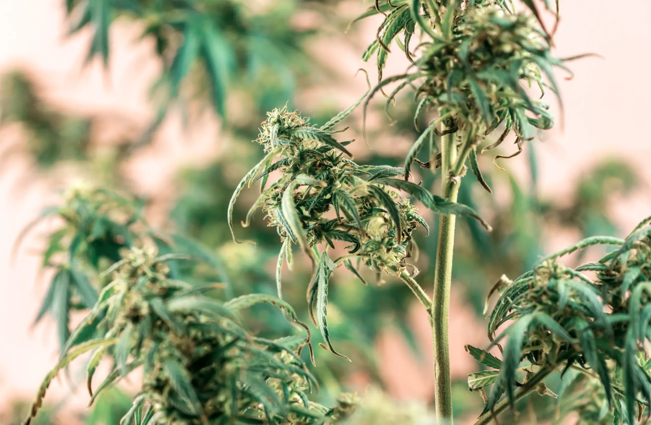
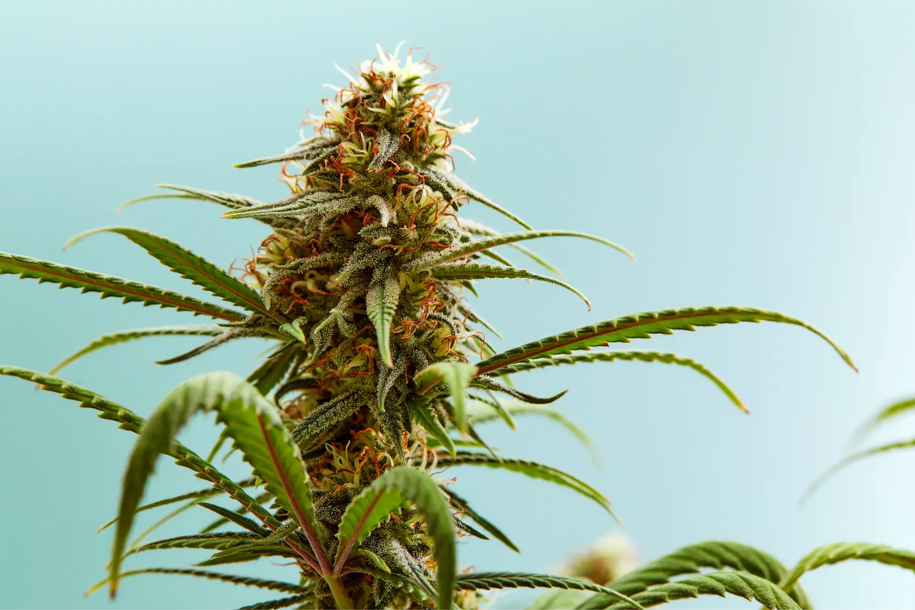
Conditioned air moving through precision horticultural ducting and return plenums, ensuring uniform temperature and vapor pressure deficit across the canopy.
Sensor placement dictates the intelligence of the entire HVACD control loop. Mounting environmental sensors on exterior room walls or directly adjacent to entrance doors guarantees skewed data. Sensors must be suspended in the central canopy zone, positioned inside active aspirated radiation shields. An aspirated shield features a miniature electric fan that continuously draws ambient canopy air across temperature and humidity transducers while shielding them from direct photon radiation emitted by LED fixtures.
Additionally, commercial HVACD installations must deploy multi-point sensor averaging. In a commercial room with 20 to 50 lighting fixtures, environmental conditions vary across microclimates. Utilizing a network of three to six aspirated sensor nodes distributed across different canopy quadrants, the central building management system (BMS) averages readings to modulate variable-air-volume (VAV) dampers and compressor staging, ensuring no localized hot spots or condensation zones develop.
Installed Sizing Workflow: Decoupling Sensible and Latent Calculations
Sizing a commercial HVACD system requires completely decoupling the sensible heat load calculation from the latent moisture load calculation. Combining these calculations into a single generic “tons of cooling” rule of thumb guarantees an imbalanced system that either overcools or under-dehumidifies. Cultivators and mechanical engineers must execute two distinct mathematical workflows.
Part 1: The Sensible Heat Calculation. Sum every source of dry thermal energy entering the space during peak photoperiod. The primary contributor is lighting wattage. Multiply total lighting electrical watts by 3.412 to convert watts into BTU/hr of sensible heat. Next, add the electrical heat output of all auxiliary equipment operating inside the space: circulation fan motors (watts multiplied by 3.412), water chiller pumps, CO2 generators, and building envelope conduction gains during hot outdoor summer days. For a 30-fixture room utilizing 680-watt LED fixtures, lighting alone generates: 30 * 680 * 3.412 = 69,605 BTU/hr of sensible heat.
| Load Category | Physical Source | Calculation Formula | Typical Commercial Value | HVACD Subsystem Addressed |
|---|---|---|---|---|
| Sensible Heat (Lights) | LED Fixtures & Ballasts | Total Watts × 3.412 BTU/hr | 65% to 75% of Sensible Load | Chilled Water / DX Evaporator Coils |
| Sensible Heat (Motors) | Circulation & Exhaust Fans | Fan Motor Watts × 3.412 BTU/hr | 10% to 15% of Sensible Load | Main Cooling Compressors |
| Latent Load (Transpiration) | Canopy Water Evaporation | Daily Gallons × 8.34 lbs × 1,061 BTU | 85% to 90% of Latent Load | Modulating Dehumidifiers & Reheat |
| Latent Load (Substrate) | Media Surface Evaporation | Estimated 10% to 15% of Daily Irrigation | 10% to 15% of Latent Load | Condensing Evaporator Coils |
| Sensible Envelope Gain | Building Wall & Roof Conduction | U-Factor × Area × Delta T | 5% to 15% of Sensible Load | Building Envelope Insulation |
| Sensible Reheat Addition | Hot-Gas Reheat Condenser | Modulated to prevent overcooling | Dynamic during dehumidification | Integrated Hot-Gas Reheat Circuit |
Part 2: The Latent Moisture Calculation. Determine the total mass of liquid water applied to the room on peak irrigation days. If the 30-light room consumes 35 gallons of water per day, that volume equates to: 35 gallons multiplied by 8.34 pounds per gallon, equaling 291.9 pounds of water vapor per day. Since water requires approximately 1,061 BTU of latent heat to vaporize one pound of liquid, the daily latent heat load is: 291.9 * 1,061 = 309,706 BTU per day. Dividing this by a 12-hour photoperiod yields an hourly latent load of 25,809 BTU/hr during lights-on.
Part 3: Calculating Total Enthalpy and Required Equipment Capacity. Adding the peak hourly sensible load (approximately 75,000 BTU/hr including fans) to the peak hourly latent load (25,809 BTU/hr) yields a total hourly cooling load of 100,809 BTU/hr. Dividing by 12,000 BTU/hr per ton of refrigeration reveals a total required cooling capacity of 8.4 tons. However, because standard commercial air conditioners provide only 20 to 25 percent latent cooling capacity, an off-the-shelf 8.5-ton AC would provide only about 20,000 BTU/hr of latent removal, falling short of the required 25,809 BTU/hr. A purpose-built horticultural HVACD system with integrated hot-gas reheat or dedicated commercial dehumidifiers is strictly required to satisfy both loads simultaneously.
Dynamic Environmental Loads: Photoperiod Inversion and Meteorological Weather
Indoor agricultural heat loads are characterized by extreme, abrupt step-changes that never occur in residential or commercial office buildings. The most violent thermodynamic event in a cannabis cultivation facility is the photoperiod transition from lights-on to lights-off.
At the exact second high-intensity LED fixtures shut down, the dry sensible heat load drops from 70,000 BTU/hr down to virtually zero. However, the root substrate, irrigation tables, and plant tissue remain warm, continuing to evaporate water into the air. If the HVACD system relies on simple cooling compressors to dehumidify, the sudden disappearance of sensible heat forces cooling coils to shut off to prevent freezing the room. Within minutes, relative humidity spikes toward 85 to 90 percent. An integrated HVACD system must instantaneously transition into pure dehumidification mode with full hot-gas reheat, maintaining air temperature while running compressors at maximum capacity to strip nocturnal moisture.
During outdoor rainstorms, our indoor sealed grow room experiences sudden humidity surges, even though the room is completely closed and we do not pull outside air. How does outdoor weather affect a sealed room?
Even in technically sealed rooms, building envelopes experience barometric pressure shifts and minor envelope infiltration through door seals, electrical conduits, and ceiling drywall joints. Furthermore, high outdoor relative humidity dramatically reduces building wall conduction losses. If outdoor air is humid and warm, heat cannot escape through exterior walls, altering the cycling frequency of your HVACD cooling compressors. If compressors cycle less frequently due to reduced wall conduction, moisture extraction drops. True sealed facilities must maintain a slight positive room pressure and utilize modulating dehumidification independent of building conduction.
Question sent by: Liam, via email.
Liam’s observation highlights the role of meteorological weather in commercial facility thermodynamics. Building envelopes act as semi-permeable thermal membranes. During cold, dry winter weather, heat and moisture naturally migrate outward through structural materials via high vapor pressure differentials. During humid summer weather or heavy rainstorms, vapor pressure gradients reverse, driving moisture inward through tiny envelope breaches.
Commercial facilities combat these weather-induced load shifts by maintaining precise room pressurization. In a sealed indoor cultivation facility with supplemental carbon dioxide enrichment, the room should be held at a neutral to slightly positive static pressure (+0.02 to +0.05 inches of water gauge) relative to adjacent corridors. This slight positive pressure prevents humid, unconditioned air or biological fungal spores from infiltrating the flowering room through structural seams and doorways.
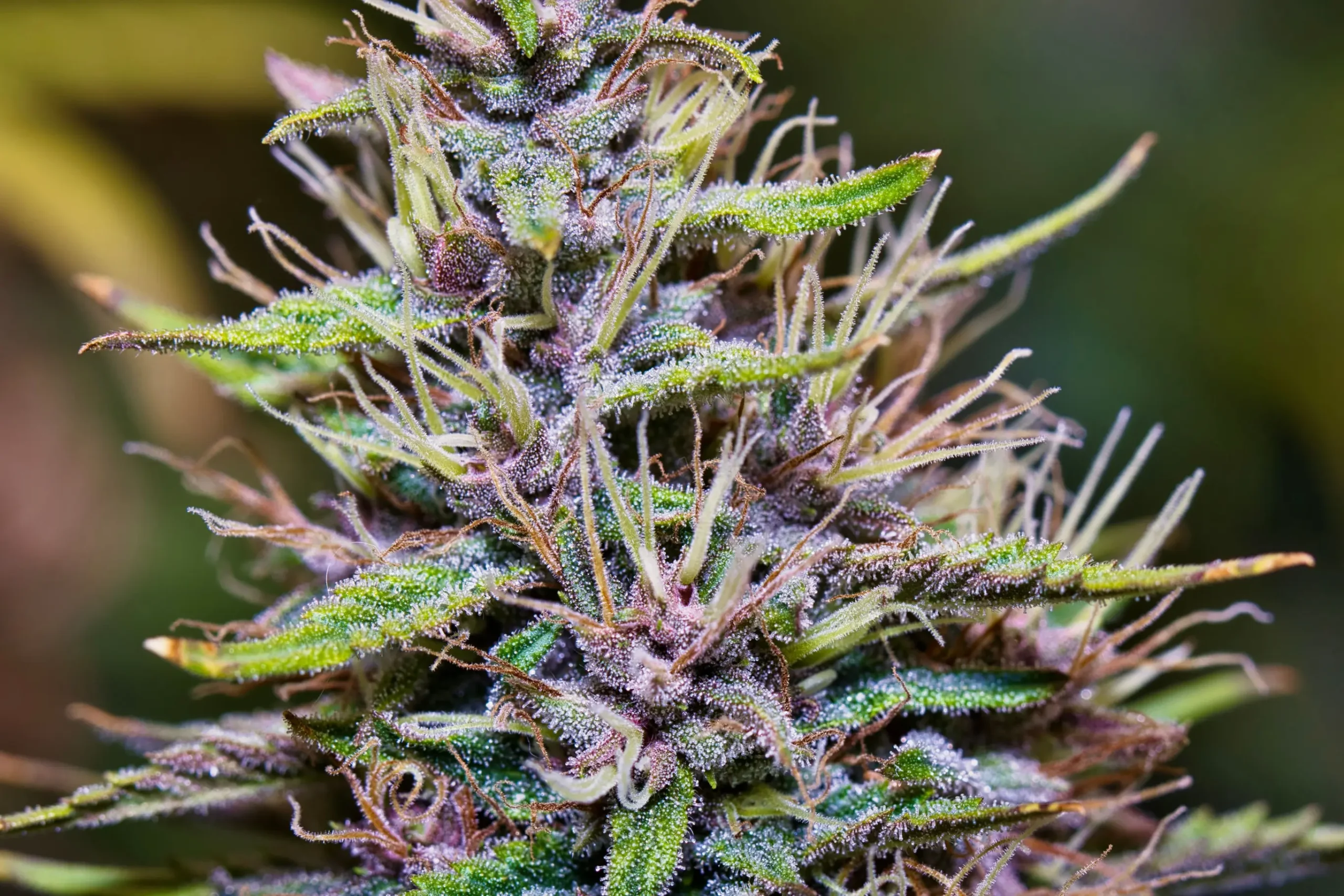
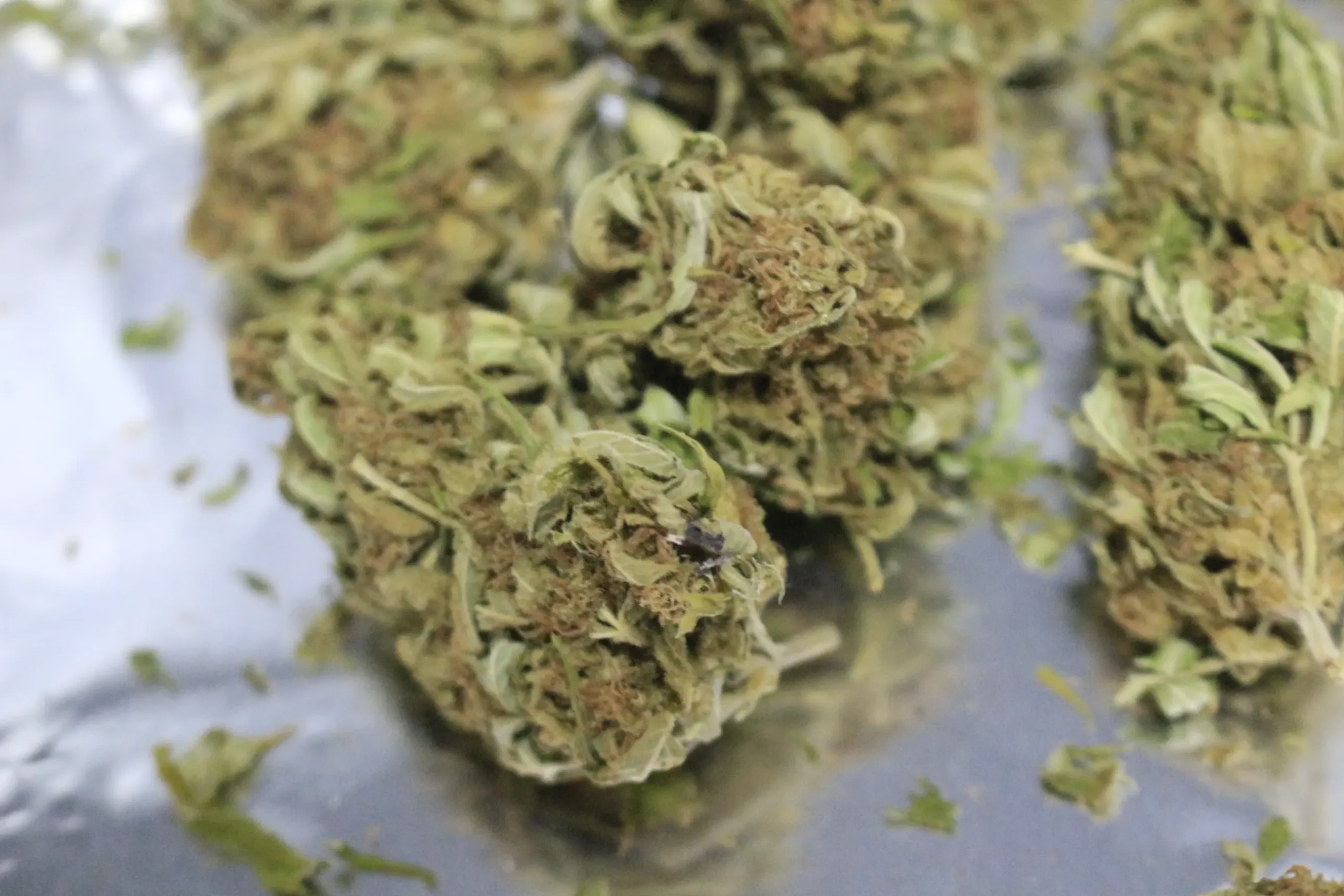
Fungal spore germination and Botrytis outbreak caused by nocturnal humidity spikes, highlighting the vital necessity of dedicated lights-off latent load extraction.
Plant phenology also drives massive dynamic load changes across the 9-week flowering cycle. During week one of flower, canopy leaf area is moderate, root systems are establishing, and daily water consumption is low. Sensible heat dominates the room. By week six, the canopy has expanded into a dense, multi-layered biomass transpiring massive volumes of water, shifting the room into a heavy latent regime. Finally, during week eight and nine, cultivators frequently implement pre-harvest drought stress or lower irrigation inputs, causing latent loads to drop while sensible heat remains constant.
An HVACD system lacking variable-capacity modulation cannot adapt to these dramatic phenological load shifts. Fixed-capacity single-stage equipment will severely over-dehumidify during early vegetative growth (causing excessive Leaf VPD and stomatal closure) and completely fail during peak flowering (causing catastrophic humidity spikes and bud rot). Variable-frequency drives (VFDs) on supply fans and modulating digital scroll compressors are essential to track these dynamic agricultural load profiles smoothly.
Failure Modes: Coil Freezing, Reheat Failures, and Controller Competition
When high-capacity mechanical equipment operates in high-humidity agricultural environments, minor mechanical and control misconfigurations quickly escalate into catastrophic failures. Recognizing these failure modes allows facility managers to implement preventative safeguards.
The most common mechanical failure is evaporator coil freezing. When return air filters become loaded with dust, loose perlite dust, or foliar debris, airflow across the evaporator coil drops significantly. Reduced airflow prevents the warm room air from transferring its heat to the cold refrigerant inside the coil tubes. Consequently, the refrigerant evaporation temperature plummets below 0 degrees Celsius (32 degrees Fahrenheit). Condensed water vapor freezes on the aluminum fins, forming an expanding sheet of solid ice that completely blocks airflow. Once frozen, moisture extraction drops to zero, and liquid refrigerant floods back to the compressor, causing catastrophic mechanical slugging and motor destruction.
Diagnostic Warning: Competitive Mechanical Cycling (Controller Fighting)
One of the most energy-wasting and destructive failure modes in unintegrated grow rooms is controller competition. This occurs when an independent air conditioner and an independent portable dehumidifier operate on separate, unlinked thermostats. The dehumidifier compressor runs, rejecting hot sensible air into the room; the air conditioner detects the rising temperature and engages its cooling compressor to pull temperatures down; the air conditioner overcools the space, triggering a third supplemental space heater to turn on. These unlinked appliances fight each other continuously, consuming tens of thousands of dollars in wasted electricity while producing wildly erratic canopy VPD.
Eliminating controller competition requires centralized building automation. A single master programmable logic controller (PLC) or specialized CEA environmental computer (such as Argus, Priva, TrolMaster, or Agrowtek) must oversee all thermal and hygrometric actuators. The central controller executes priority logic: when humidity rises, it modulates the cooling coil and hot-gas reheat simultaneously, ensuring that temperature setpoints and humidity setpoints are satisfied in coordinated harmony without competing mechanical cycles.
Another prevalent failure mode is hot-gas reheat valve sticking. Reheat circuits utilize modulating three-way solenoid valves or electronic stepper expansion valves to divert hot discharge gas from the compressor into the reheat coil. Over thousands of operational cycles, mechanical valve stems can bind or collect debris from refrigeration lines. If a reheat valve sticks open during lights-on when full sensible cooling is needed, the unit continuously heats its own supply air, causing the room to overheat uncontrollably. Installing high-temperature discharge safety cutoffs prevents room thermal runaway.
Empty-Room Commissioning and Psychrometric Stress Testing
Before introducing crops into a newly constructed or retrofitted commercial facility, the entire HVACD infrastructure must undergo comprehensive commissioning under full artificial load. Commissioning verifies that duct static pressures, airflow distribution, cooling capacity, and reheat modulation perform precisely according to engineering design specifications.
Begin by conducting the duct air balance test. Utilize a calibrated airflow capture hood or hot-wire anemometer to measure the volumetric airflow (CFM) delivered by every individual supply diffuser and linear fabric run. Adjust manual balancing dampers until every zone receives its designed airflow within a tolerance of plus or minus 5 percent. Verify that total external static pressure at the air handler blower does not exceed the manufacturer maximum rating.
- Airflow Capture Hood Balancing: Verify supply air delivery matches engineering CFM specifications across all diffusers.
- Full Electrical Load Thermal Scan: Conduct infrared thermography on all electrical panels, contactors, and disconnect switches.
- Artificial Sensible Load Test: Power on all lighting arrays at 100% capacity for 8 continuous hours to verify cooling stability.
- Artificial Latent Stress Test: Introduce calculated peak moisture load via steam or ultrasonic humidifiers to test dehumidification.
- Hot-Gas Reheat Modulation Audit: Confirm reheat valves engage smoothly without hunting or inducing room temperature swings.
- Lights-Off Transition Dampening: Verify zero humidity spike (< 4% RH change) during simulated abrupt lights-out transition.
- Emergency High-Temp Shutdown: Test automated lighting contactor kill-switches when room temperature is artificially driven past 32 °C.
Executing this commissioning checklist identifies mechanical flaws before live crops are placed at risk. During the artificial load testing, technicians should utilize an infrared thermographic camera to scan all electrical distribution panels, breaker lugs, and compressor contactors under full operating load. High-resistance electrical connections manifest as bright thermal anomalies, allowing electricians to torque loose terminal lugs and replace defective contactors before they cause arc-flash fires or equipment shutdown.
The commissioning protocol must also rigorously test automated safe-failure sequences. Simulate an emergency loss of chilled water or compressor failure by tripping the primary equipment disconnect. The central environmental controller must instantly detect the thermal rise, trigger high-priority SMS alerts to facility operators, and initiate automated protective sequences: immediately dimming lighting arrays to 20 percent power or shutting off lights entirely to prevent catastrophic canopy heat scorching.
Preventative Maintenance Schedule and Long-Term Reliability
Commercial HVACD systems represent the most expensive capital investment within an indoor cultivation facility. Maintaining continuous reliability requires a disciplined, scheduled preventative maintenance protocol executed by qualified internal technicians or certified HVAC contractors.
Establish a monthly mechanical inspection schedule. Inspect and replace air filters across all air handling units and dehumidifiers. High-performance cultivation rooms should maintain a multi-stage filtration strategy, utilizing low-cost MERV 8 pre-filters to capture coarse dust and perlite particulates, followed by high-capacity MERV 13 secondary filters to capture fungal spores and bacteria. Replacing pre-filters monthly prevents static pressure from choking supply blowers and protects delicate evaporator coil fins from fouling.
Maintenance Protocol: Condensate Trap Priming and Microbial Disinfection
Evaporator coil condensate drain pans operate under negative air pressure relative to the surrounding room. If the drain line P-trap dries out or is improperly configured, the blower vacuum sucks sewer gases and microbial contaminants into the supply air stream while preventing condensate water from draining out of the pan. Standing water overflows into the ductwork, breeding toxic mold colonies. Every 30 days, inspect and prime all condensate P-traps with clean water, flush drain lines with a biological enzyme cleaner or dilute peroxide solution, and inspect float switches for free mechanical movement.
Quarterly maintenance must include a complete refrigeration and mechanical audit. Certified technicians must measure compressor suction and discharge pressures, calculate superheat and subcooling values, and inspect sight glasses for moisture contamination or refrigerant bubbles. Measure the electrical operating current (amperage) on all blower motors, compressor windings, and condenser fans, comparing readings against manufacturer nameplate full-load amps (FLA). Inspect drive belts on centrifugal blowers for tension, alignment, and wear, replacing cracked or glazed belts to prevent catastrophic airflow failure.
By understanding the profound thermodynamic differences between sensible and latent loads, designing systems around the low Sensible Heat Ratios inherent to indoor horticulture, integrating modulating hot-gas reheat, and executing rigorous commissioning and preventative maintenance, commercial cannabis cultivators achieve absolute environmental mastery. The cultivation facility maintains rock-solid temperature and vapor pressure deficit stability across every hour of the crop cycle, banishing fungal disease, maximizing photosynthetic efficiency, and unlocking the full genetic expression and commercial yield of premium botanical crops.
Scientific and Technical References
- ASHRAE. (2019). ASHRAE Handbook: HVAC Applications (SI Edition). Chapter 24: Plant Environments. American Society of Heating, Refrigerating and Air-Conditioning Engineers. The definitive engineering reference for sensible and latent load calculations, sensible heat ratios, and HVAC design in indoor plant facilities.
- Both, A. J., Benjamin, L., Ciolkosz, D., & Kleinhenz, M. D. (2015). Greenhouse Dehumidification: Principles and Practices. Rutgers University Cooperative Extension Bulletin E353. Engineering analysis of moisture removal, psychrometrics, and energy efficiency metrics in controlled environment horticulture.
- Albright, L. D. (1990). Environment Control for Animals and Plants. American Society of Agricultural and Biological Engineers. Foundational text covering psychrometric processes, sensible and latent heat transfer equations, and ventilation thermodynamics.
- Taiz, L., Zeiger, E., Møller, I. M., & Murphy, A. (2015). Plant Physiology and Development (6th ed.). Sinauer Associates. In-depth analysis of foliar energy balance, stomatal conductance, transpirational cooling, and latent heat conversion under artificial light spectra.
Share this article
A quick overview of the topics covered in this article.
Follow us
Latest articles

November 6, 2026

November 6, 2026

November 6, 2026