
Grow Tent Too Hot: Diagnosis Before Buying a Bigger Fan
When canopy temperatures spike past 30 degrees Celsius (86 degrees Fahrenheit) inside an indoor cultivation enclosure, the immediate impulse for most growers is to rush online and purchase a larger inline exhaust fan. However, upgrading from a 4-inch fan to a 6-inch or 8-inch unit frequently fails to solve chronic overheating issues. In high-performance horticultural environments, thermal buildup is rarely caused by insufficient fan horsepower alone. Instead, excessive heat is almost invariably the biological and mechanical symptom of unaddressed thermal bottlenecks: restrictive ducting bends, heat-soaking LED drivers trapped inside the tent, choked passive intake vents, or an intake air source that is fundamentally too warm.
Buying an oversized exhaust fan without diagnosing the true root cause often exacerbates environmental instability. High-velocity fans pull extreme negative pressure against tent fabric walls, collapse intake ducting, dramatically increase operational acoustics, strip the boundary layer from delicate foliage, and exhaust costly carbon dioxide before plants can assimilate it. Before spending capital on redundant mechanical upgrades, cultivators must execute a systematic diagnostic protocol to measure installed airflow impedance, evaluate sensible heat distribution, and eliminate thermal loads at the source.
Thermodynamic Principle: The Sensible Heat Removal Equation
The rate at which an exhaust ventilation system removes sensible thermal energy from an enclosed space is governed by the fundamental thermodynamic relationship: Heat Removal (BTU/hr) equals 1.08 multiplied by Airflow (CFM) multiplied by Delta T (the temperature difference between exhaust air and incoming intake air). If the temperature differential between your lung room and your grow tent is less than 3 to 4 degrees Celsius, increasing CFM produces rapidly diminishing returns. You cannot cool a grow tent below the ambient temperature of its intake supply air without mechanical air conditioning or heat exchange.
Understanding this sensible heat equation is essential for accurate troubleshooting. When a grower reports that an enclosure remains at 32 degrees Celsius despite a commercial mixed-flow fan running at maximum revolutions per minute, measuring the intake temperature almost always reveals a lung room hovering at 29 degrees Celsius. In this thermodynamic reality, no fan on earth, regardless of diameter or static pressure rating, can pull the tent down into the ideal 24 to 26 degrees Celsius range. The primary diagnostic variable is not fan capacity; it is the intake thermal baseline and the effective heat transfer differential.
Furthermore, cultivators must distinguish between ambient air temperature and foliar canopy temperature. Modern high-output LED fixtures emit intense photosynthetically active radiation (PAR) with minimal radiant infrared heat compared to legacy high-pressure sodium (HPS) fixtures. Consequently, an ambient air temperature of 28 degrees Celsius under LEDs often maintains a foliar leaf surface temperature of 26 degrees Celsius due to active transpirational cooling. Rushing to depress air temperatures without verifying leaf surface temperature can inadvertently suppress metabolic activity and stall floral development.
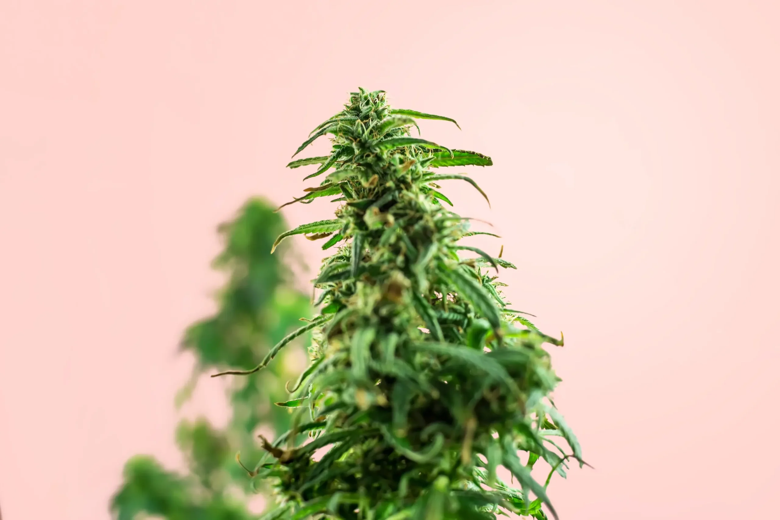
To accurately assess foliar stress, growers must deploy hand-held non-contact infrared thermometers or permanent infrared thermal radiometers aimed directly at the upper sun leaves. When leaf temperatures exceed 29 degrees Celsius under high-intensity illumination, the plant stomatal defense mechanism activates. Guard cells lose turgor pressure, stomatal pores close, and the transpiration stream that pulls essential dissolved calcium and nitrate ions through the vascular xylem collapses. This failure cascade triggers acute tip burn, leaf cupping, and reduced photosynthetic carbon assimilation.
Conversely, if an uncalibrated wall sensor reads 29 degrees Celsius but infrared leaf inspection reveals a healthy foliar temperature of 26.5 degrees Celsius, the crop is thriving within optimal metabolic parameters. In such cases, purchasing an aggressive exhaust fan would disrupt the delicate boundary layer, waste electrical power, and introduce unnecessary acoustic vibration. Accurate diagnostics must always validate biological leaf conditions before modifying environmental machinery.
Defining the Thermal Problem and Controlling Variables
A Structured Heat Diagnosis Begins by Isolating
A structured heat diagnosis begins by isolating the specific thermodynamic and fluid dynamic variables governing the grow room microclimate. The key controlling parameters include volumetric airflow rate (CFM), system static pressure impedance (water gauge inches or Pascals), intake-to-exhaust thermal delta, sensible heat dissipation from equipment, and relative humidity (which dictates the cooling capacity of foliar transpiration).
When diagnosing an overheating enclosure, growers must determine whether the failure represents a mass air exchange deficiency or an excessive heat generation load. An air exchange deficiency occurs when the installed exhaust fan cannot deliver its rated volumetric flow rate due to duct friction, restrictive carbon filter beds, or insufficient intake aperture area. A heat generation overload occurs when sensible heat emissions from LED driver ballasts, dehumidifier compressors, and submerged water pumps overwhelm the thermal dissipation capacity of the intake air volume.
“My 4×4 grow tent is reaching 33 degrees Celsius under a 650-watt LED fixture. I have a 4-inch inline fan running at 100% speed through a carbon filter. Should I replace it with an 8-inch fan to bring temperatures down to 25 degrees Celsius?”
Question sent by: Logan Carmichael, via email.
Before replacing your fan, measure the temperature of the room your tent pulls air from. If that room is 27 degrees Celsius, even an 8-inch fan cannot pull the tent down to 25 degrees Celsius. Next, inspect your 4-inch ducting: if you have multiple 90-degree bends and a dense carbon filter, your fan may be delivering less than 80 CFM against high static pressure. Relocating your LED driver ballast outside the tent will immediately eliminate 15 to 20 percent of your heat load without spending money on a new fan.
Marcuss Scenario Represents the Classic Diagnostic Crossroads
Marcus’s scenario represents the classic diagnostic crossroads experienced by thousands of indoor cultivators. An inline fan operating against severe duct resistance experiences aerodynamic stall. In a 4-inch ventilation run with two flexible accordion bends and an unmaintained carbon pre-filter, static pressure can easily exceed 0.75 inches of water gauge. Under these restrictive conditions, typical mixed-flow fan impellers lose over 60 percent of their rated volumetric output, reducing what should be a robust air exchange to an ineffective trickle.
Furthermore, running a 650-watt LED fixture generates approximately 2,218 BTU of sensible heat per hour. The heavy aluminum driver ballast alone contributes between 15 and 20 percent of this total thermal output. In an enclosed 4×4 grow tent, trapping that driver inside the ceiling space directly beneath the exhaust intake creates a superheated thermal pocket that radiates heat back down onto the plant canopy. Simply detaching the driver and mounting it outside the tent removes up to 440 BTU per hour of heat without altering the ventilation system.
System Layout: Aerodynamic Friction, Intake Path, and Equipment Placement
Airflow Layout Geometry
Airflow layout geometry dictates whether an inline fan operates efficiently along its optimal performance curve or struggles in a high-resistance thermal loop. Every physical element within the airflow path introduces friction loss that opposes the movement of air. Cultivators must audit the complete physical loop: passive intake louvers, internal circulation fans, lighting heat sinks, carbon filter positioning, exhaust fan mounting, duct transitions, and external building terminations.
The most common layout flaw in amateur grow tents is an undersized intake pathway. Fluid dynamics dictates that for air to exit an enclosure, an equivalent mass of air must enter. When passive intake openings are smaller than the exhaust duct cross-sectional area, the exhaust fan creates extreme negative static pressure. The flexible walls of the grow tent suck inward, reducing usable cultivation volume, pinching duct collars, and straining fan motor windings. To maintain optimal airflow velocity without excessive static resistance, passive intake aperture area must be at least two to three times the cross-sectional area of the exhaust duct.
“When working on airflow layout geometry in my home grow, how do I know if my current setup is drifting out of range before visible plant stress appears?”
Question sent by: BendBasementBuds, via contact form.
Start by taking a direct baseline measurement rather than guessing from foliar symptoms alone. In practice, When passive intake openings are smaller than the exhaust duct cross-sectional area, the exhaust fan creates extreme negative static pressure.
Once you have confirmed the baseline reading, adjust only one variable at a time and log the response over the next 24 to 48 hours. Securing ducting taut with metal hose clamps and heavy-duty zip ties ensures laminar flow and eliminates the backpressure that chokes exhaust fan performance.
Duct installation quality is frequently the hidden culprit behind high canopy temperatures. When flexible aluminum ducting is loosely strung across tent roof poles with deep sags, air experiences intense boundary layer turbulence. Micro-vortices form along the internal wire coils, converting dynamic air velocity into unusable heat and static drag. Securing ducting taut with metal hose clamps and heavy-duty zip ties ensures laminar flow and eliminates the backpressure that chokes exhaust fan performance.
Equipment Placement Inside the Grow Tent Also
Equipment placement inside the grow tent also plays a massive role in thermal stratification. Warm air naturally rises due to thermal buoyancy, accumulating in the upper third of the tent volume. The carbon filter and exhaust intake should always be suspended at the highest physical point in the ceiling space, directly extracting this superheated air plume before it can mix back into the plant canopy. Placing the exhaust intake low or in the center of the tent short-circuits ventilation, leaving an intense thermal dome trapped directly under the light fixtures.
Aerodynamic Rule: Equivalent Duct Length and Bend Penalties
In flexible ducting runs, every sharp 90-degree elbow introduces aerodynamic resistance equivalent to 20 to 25 linear feet of straight, smooth-walled rigid duct. Utilizing sagging, un-stretched accordion ducting compounds friction losses by an additional 50 percent. If your exhaust line contains three flexible bends and ten feet of loose ducting, your inline fan experiences the friction penalty of over 85 feet of pipe. Straightening duct lines, stretching flexible sleeves taut, and replacing tight elbows with wide-radius sweeps will restore up to 40 percent of lost CFM instantly.
Circulation Fan Positioning Within the Canopy
Circulation fan positioning within the canopy must be coordinated with the exhaust pathway to prevent thermal short-circuiting. If oscillating clip fans are angled upward toward the carbon filter, they disrupt the natural thermal buoyancy gradient, blowing heated air back down across the top colas. Circulation fans should be oriented to create horizontal, undulating air movement through the foliage, gently sweeping transpirational moisture away from leaf undersides while allowing warm air to rise unhindered toward the ceiling exhaust.
Furthermore, passive intake vents must be positioned at the bottom of the enclosure on the opposite side of the exhaust port. This diagonal intake-to-exhaust architecture forces cool incoming air to sweep across the lower root containers, rise through the vegetative canopy, absorb sensible heat from the LED fixtures, and exit smoothly through the ceiling exhaust. Positioning intake ports directly beneath or adjacent to the exhaust creates a direct short-circuit where cool intake air is sucked immediately out of the tent without cooling the plant canopy.
Installed Sizing and Measurement Workflow: Escaping Marketing Shortcuts
A Fatal Mistake in Environmental Troubleshooting
A fatal mistake in environmental troubleshooting is relying on manufacturer “free-air” CFM ratings. A budget 6-inch inline fan advertised at 400 CFM achieves that figure only when suspended in an open room with zero attached ducting, zero carbon filters, and zero static backpressure. Once installed inside an operational grow tent with a packed virgin carbon filter bed, twenty feet of ribbed ducting, and an external backdraft damper, that same fan may deliver less than 180 CFM.
To accurately diagnose whether your existing fan is mechanically undersized or simply strangled by system resistance, cultivators must execute an installed sizing workflow based on physical thermal dissipation rather than basic room-volume shortcuts (such as the simplistic “exchange room air once per minute” rule). The room volume shortcut completely ignores lighting wattage, ambient lung room temperatures, and duct friction coefficients.
“I am trying to dial in a fatal mistake in environmental troubleshooting for my indoor tent, what is the most reliable measurement to check first so I do not overcorrect?”
Question sent by: Logan Dahlberg, via email.
Start by taking a direct baseline measurement rather than guessing from foliar symptoms alone. In practice, A budget 6-inch inline fan advertised at 400 CFM achieves that figure only when suspended in an open room with zero attached ducting, zero carbon filters, and zero static backpressure.
Once you have confirmed the baseline reading, adjust only one variable at a time and log the response over the next 24 to 48 hours. If your installed 4-inch fan delivers only 120 CFM against restrictive ducting, the air temperature inside the tent will inevitably rise by 12.6 degrees Fahrenheit above lung room ambient.
| Diagnostic Checkpoint | Measured Variable | Normal Operating Range | Overheating Failure Threshold | Corrective Action |
|---|---|---|---|---|
| Intake Supply Air | Lung Room Temperature | 18 to 22 °C (64 to 72 °F) | > 26 °C (79 °F) | Condition lung room via AC or fresh cool intake ducting. |
| LED Driver Placement | Sensible Thermal Radiation | External mounting preferred | Driver inside tent near canopy | Detach driver ballast and mount outside grow tent structure. |
| Duct Geometry | Total Equivalent Length | < 30 equivalent feet | > 60 equivalent feet (tight bends) | Straighten duct lines; replace 90° elbows with 45° sweeps. |
| Carbon Filter Bed | Differential Static Pressure | 0.15 to 0.35 in. w.g. | > 0.60 in. w.g. (clogged pre-filter) | Wash or replace dust pre-filter sleeve; replace saturated carbon. |
| Passive Intake Ratio | Intake-to-Exhaust Aperture | 2:1 to 3:1 area ratio | < 1:1 area ratio (extreme vacuum) | Open lower mesh intake vents or add dedicated light-trapped duct ports. |
| Canopy Leaf Delta | Leaf Surface vs Air Temp | -1.5 to -2.5 °C (under LED) | > +1.0 °C (stomata closed) | Verify irrigation EC; lower light intensity; restore root hydration. |
The Diagnostic Table Above Illustrates Why Jumping
The diagnostic table above illustrates why jumping immediately to a larger exhaust fan is often premature. In more than 70 percent of indoor overheating investigations, the issue can be resolved entirely by addressing three mechanical adjustments: detaching LED drivers, opening lower intake ports to eliminate wall-sucking negative pressure, and washing dusty carbon filter pre-sleeve jackets.
To calculate the true required volumetric airflow for sensible heat removal, cultivators should apply the engineering formula: Required CFM equals Total Heat Load (BTU/hr) divided by (1.08 multiplied by Target Delta T in degrees Fahrenheit). For a 480-watt LED fixture generating approximately 1,638 BTU/hr of sensible heat, assuming an acceptable temperature rise of 5 degrees Fahrenheit between intake and exhaust, the formula yields: 1,638 / (1.08 * 5) = 303 CFM of installed, real-world airflow. If your installed 4-inch fan delivers only 120 CFM against restrictive ducting, the air temperature inside the tent will inevitably rise by 12.6 degrees Fahrenheit above lung room ambient.
Dynamic Thermal Loads: Photoperiod, Transpiration, Weather, and Room Architecture
Thermal Dynamics Inside a Cannabis Grow Tent
Thermal dynamics inside a cannabis grow tent are never static. They shift continuously across photoperiod transitions, plant maturation stages, external meteorological weather events, and residential building thermal cycles. An environmental ventilation setup that functions flawlessly in late November during vegetative growth can collapse catastrophically in mid-July when mature flowering plants fill the enclosure.
During the vegetative stage, plant biomass is relatively small, transpirational water evaporation is moderate, and light intensity is often dimmed to 50 or 60 percent of maximum output. Under these low-load conditions, minor mechanical airflow deficiencies remain completely masked. However, as plants transition into peak floral bloom, lighting fixtures are ramped to 100 percent intensity, generating maximum sensible heat dissipation. Simultaneously, mature root systems drink several liters of water daily, transpirating immense volumes of moisture into the air.
“My grow tent temperatures are fine during the winter, but during summer afternoons the tent hits 34 degrees Celsius even though my exhaust fan is screaming at 100%. Why is my ventilation suddenly failing?”
Question sent by: Logan Caruso, via contact form.
Your ventilation system has not mechanically failed; the thermal baseline of your intake air has shifted. When outdoor summer temperatures rise, the ambient room housing your grow tent absorbs heat through exterior walls and windows. If your lung room temperature climbs from 20 degrees Celsius in winter to 28 degrees Celsius in summer, your exhaust fan simply pulls 28-degree air into a space being heated by high-intensity lamps. You must cool the lung room with an air conditioner or switch your lighting photoperiod to run exclusively during cooler nighttime hours.
Elena’s inquiry highlights the fundamental role of room architecture and seasonal meteorological load. Grow tents installed in attics, uninsulated garages, or south-facing residential bedrooms experience massive external solar thermal gain during summer months. In these environments, the building envelope acts as a thermal capacitor, soaking up solar radiation throughout the afternoon and radiating heat into the room.
One of the Most Cost-effective Diagnostic Operational
One of the most cost-effective diagnostic operational corrections for summer heat spikes is photoperiod scheduling inversion. By programming digital light timers to operate between 8:00 PM and 8:00 AM (or 9:00 PM and 9:00 AM), lighting heat is generated during the coolest ambient hours of the diurnal cycle. During the hot daylight hours, the grow lights are powered off, allowing the tent to remain dormant when ambient building temperatures peak. This operational adjustment immediately eliminates 6 to 8 degrees Celsius of peak thermal stress without spending a single dollar on equipment.

Transpirational Cooling Is Natures Built-in Evaporative Cooling
Transpirational cooling is nature’s built-in evaporative cooling mechanism. When water evaporates through stomatal pores, it absorbs latent heat of vaporization (approximately 2,260 Joules per gram of water), cooling the foliar tissue below ambient air temperature. A vigorous, fully hydrated cannabis canopy transpiring four gallons of nutrient solution daily provides over 30,000 BTU of natural latent cooling across a 24-hour cycle. However, if root substrates dry out or if root-zone electrical conductivity (EC) climbs too high, root osmotic pressure drops. The plant cannot pull water fast enough to satisfy transpirational demand, stomata snap shut to prevent desiccation, and foliar temperatures immediately spike 3 to 4 degrees Celsius above the surrounding air.
Before purchasing an expensive fan upgrade, growers must verify root-zone hydration and irrigation runoff electrical conductivity. If plants are experiencing localized root drought or osmotic lockup, re-establishing optimal root-zone moisture tension and flushing accumulated fertilizer salts will restore transpirational cooling, immediately dropping canopy leaf surface temperatures back into the safe biological zone.
Failure Modes: Short-Circuit Airflow, Negative Pressure Errors, and Sensor Bias
When Systematic Diagnosis Confirms That Intake Ambient
When systematic diagnosis confirms that intake ambient temperatures and lighting loads are within reasonable theoretical limits, cultivators must examine common physical failure modes within the mechanical installation. These aerodynamic and electronic errors can completely neutralize the cooling capacity of an otherwise capable inline fan.
Thermal short-circuiting occurs when exhaust air discharged from the grow tent is inadvertently drawn back into the passive intake ports. This disastrous recirculation loop frequently develops when growers vent exhaust air directly into the same room where the tent is situated without ducting it away from intake vents. Within hours, the tent consumes its own heated, moisture-laden exhaust air, causing temperatures and humidity to spiral upward in a compounding thermal feedback loop. Exhaust air must always be ducted to a remote room, an exterior building vent, or at least opposite corners of the lung room separated by physical baffles.
Diagnostic Warning: Unshielded Sensor Radiation Bias
Hanging a bare environmental sensor probe directly beneath high-intensity LED light bars produces severe radiation bias errors. The dark plastic casing of the sensor absorbs radiant photons directly, heating the internal thermistor far above true ambient air temperature. Growers routinely panic over sensor readings displaying 32 degrees Celsius when actual air temperature is a comfortable 26 degrees Celsius. Environmental sensors must always be housed inside an aspirated radiation shield or positioned in permanent ambient shade with continuous canopy airflow.
Sensor Placement Errors
Sensor placement errors represent one of the most common false-positive overheating diagnoses in modern indoor cultivation. Solid-state humidity and temperature sensors suspended in direct light act like miniature solar ovens. Direct photon absorption heats the plastic sensor housing, biasing temperature readings upward by as much as 4 to 6 degrees Celsius and skewing relative humidity downward by 15 to 20 percent. Cultivators who make mechanical purchase decisions based on biased sensor readings spend hundreds of dollars fixing an environmental problem that does not actually exist.
Another major failure mode is carbon filter saturation and dust choking. Virgin activated carbon beds are engineered to allow air to permeate through millions of microscopic micropores. Over several months of cultivation, airborne dust, pulverised substrate perlite, organic pollen, and dried humidifier mineral scale coat the outer fabric pre-filter sleeve. Once the pre-filter becomes choked, airflow resistance spikes exponentially. The inline fan motor spins at full speed, generating loud acoustic noise and consuming maximum wattage, but moves virtually zero air across the canopy. Simply slipping off the fabric pre-filter, hand-washing it in warm water, and air-drying it restores system CFM in minutes.
Comprehensive Commissioning Test and Safe-Failure Planning
Before Concluding an Environmental Diagnosis or Committing
Before concluding an environmental diagnosis or committing to machinery replacements, cultivators should execute a structured commissioning test to benchmark system cooling performance under controlled, repeatable conditions. This diagnostic verification must be conducted across both empty-tent baseline conditions and full-canopy operational runs.
Begin by measuring the baseline lung room temperature and relative humidity with a calibrated thermo-hygrometer. Next, inspect all duct connections, ensuring that metallic worm-gear clamps are securely tightened over rubberized collars to prevent exhaust leakage. Power on the exhaust fan to 100 percent speed and perform the negative pressure deflection test: observe the flexible fabric walls of the grow tent. The walls should pull inward slightly, confirming positive negative pressure (which prevents odor escape), but should never suck inward so severely that they contact plant foliage or bow structural corner poles.
Standard Operating Verification Checklist
- Intake-to-Exhaust Delta Check: Verify temperature difference between lung room intake and tent exhaust remains below 4 °C.
- Negative Pressure Visual Audit: Ensure tent walls exhibit mild inward deflection without structural deformation or pole bowing.
- LED Driver Thermal Isolation: Confirm driver ballasts are mounted externally on fire-resistant backing boards or isolated with dedicated heat sinks.
- Duct Tension and Bend Inspection: Verify all flexible ducting runs are pulled completely taut with zero 90-degree kinked elbows.
- Aspirated Sensor Housing Audit: Confirm main environmental transducer is shaded from direct LED radiation and receives gentle airflow.
- Foliar Infrared Validation: Measure leaf surface temperature across top canopy colas to ensure readings are 1.5 to 2.5 °C below air temp.
- High-Temperature Failsafe Automation: Program electronic controller to trigger emergency exhaust override or light dimming at 31 °C.
Executing This Commissioning Checklist Eliminates Guesswork
Executing this commissioning checklist eliminates guesswork and protects valuable botanical crops from catastrophic heat stress. Integrating high-temperature failsafe programming into smart environmental controllers provides an automated safety net. If a mechanical exhaust fan motor suffers bearing seizure or a duct collar slips off during the middle of the photoperiod, the controller automatically dims the LED lighting fixture to 20 percent power or shuts it down completely when ambient canopy temperatures exceed 31 degrees Celsius, preventing catastrophic crop scorching.
Furthermore, cultivators should test safe-failure protocols by simulating fan power interruptions. Disconnect the inline exhaust fan while lights operate at 100 percent power and monitor the rate of thermal rise using a digital data logger. In a well-designed enclosure with adequate thermal mass and proper ceiling clearance, temperatures should rise gradually, giving automated monitoring systems and remote smartphone alerts sufficient time to notify the grower before thermal thresholds are breached.
Preventative Maintenance Schedule and Performance Verification
Achieving Stable, Repeatable Thermal
Achieving stable, repeatable thermal control requires regular maintenance routines that prevent the gradual accumulation of aerodynamic resistance. Dust, plant debris, and mechanical wear steadily degrade ventilation efficiency over time, turning a once-optimized grow tent into an overheating struggle.
Establish a monthly maintenance routine between cropping cycles. Disconnect and inspect inline fan impeller blades for dust accumulation. Even a thin layer of particulate matter clinging to curved backward-inclined impeller blades disrupts aerodynamic lift, inducing air turbulence, increasing motor operating temperatures, and reducing volumetric airflow output by 15 to 25 percent. Wipe fan blades clean with a microfiber cloth dampened with isopropyl alcohol, ensuring that the motor housing spins freely without mechanical grinding or shaft runout.
Field Advice: Maintenance Protocol: Carbon Filter Pre-Sleeve and Duct Sanitization. Every 60 to 90 days, remove the white polyester pre-filter sleeve from your carbon filter. Submerge and gently hand-wash the sleeve in warm water with a mild fragrance-free detergent to dissolve accumulated dust, grease, and humidifier mineral scale. Rinse thoroughly and allow the pre-filter to air-dry completely before reinstalling. Inspect flexible duct interiors for tears, perforations, or dust buildup. Replacing damaged duct sections and sanitizing fan components ensures peak aerodynamic velocity, protects motor longevity, and maintains maximum sensible heat removal efficiency throughout every harvest cycle.
Electronic Calibration Checks
In addition to physical cleaning, electronic calibration checks must be performed on all temperature and humidity transducers at least quarterly. Solid-state capacitive humidity sensors and NTC thermistors are susceptible to calibration drift when continuously exposed to airborne organic terpenes and high relative humidity. Placing sensors in a sealed container alongside a saturated sodium chloride salt slurry (which produces a constant 75 percent relative humidity reference at 25 degrees Celsius) verifies transducer accuracy and prevents false-positive climate controller responses.
By executing a thorough, systematic diagnosis before spending capital on a larger exhaust fan, cultivators identify the true physical bottlenecks restricting heat transfer. Relocating remote LED drivers, optimizing duct geometry, expanding passive intake apertures, shading environmental sensors, and maintaining clean filter media reliably lowers grow tent temperatures into the ideal physiological sweet spot. Cultivators preserve equipment budgets, reduce operational electrical costs, minimize fan acoustics, and establish the rock-solid environmental foundation required for bountiful, high-terpene cannabis harvests.
Scientific References
- Nelson, P. V. (2012). Greenhouse Operation and Management (7th ed.). Prentice Hall. Detailed analysis of greenhouse and indoor horticultural sensible heat removal equations, ventilation air exchange rates, and solar thermal gain dynamics.
- Albright, L. D. (1990). Environment Control for Animals and Plants. American Society of Agricultural and Biological Engineers (ASABE). Foundational engineering principles governing fluid dynamics, duct friction loss coefficients, and fan performance curves.
- Taiz, L., Zeiger, E., Møller, I. M., & Murphy, A. (2015). Plant Physiology and Development (6th ed.). Sinauer Associates. Comprehensive research into foliar boundary layer resistance, stomatal conductance, and transpirational evaporative cooling mechanisms under high-intensity radiation.
- ASHRAE. (2021). ASHRAE Handbook: Fundamentals (SI Edition). American Society of Heating, Refrigerating and Air-Conditioning Engineers. Engineering standards for psychrometrics, duct equivalent lengths, and fan-duct static pressure interaction.
Share this article
A quick overview of the topics covered in this article.
Follow us
Latest articles
November 7, 2026
November 7, 2026
November 7, 2026
November 7, 2026