
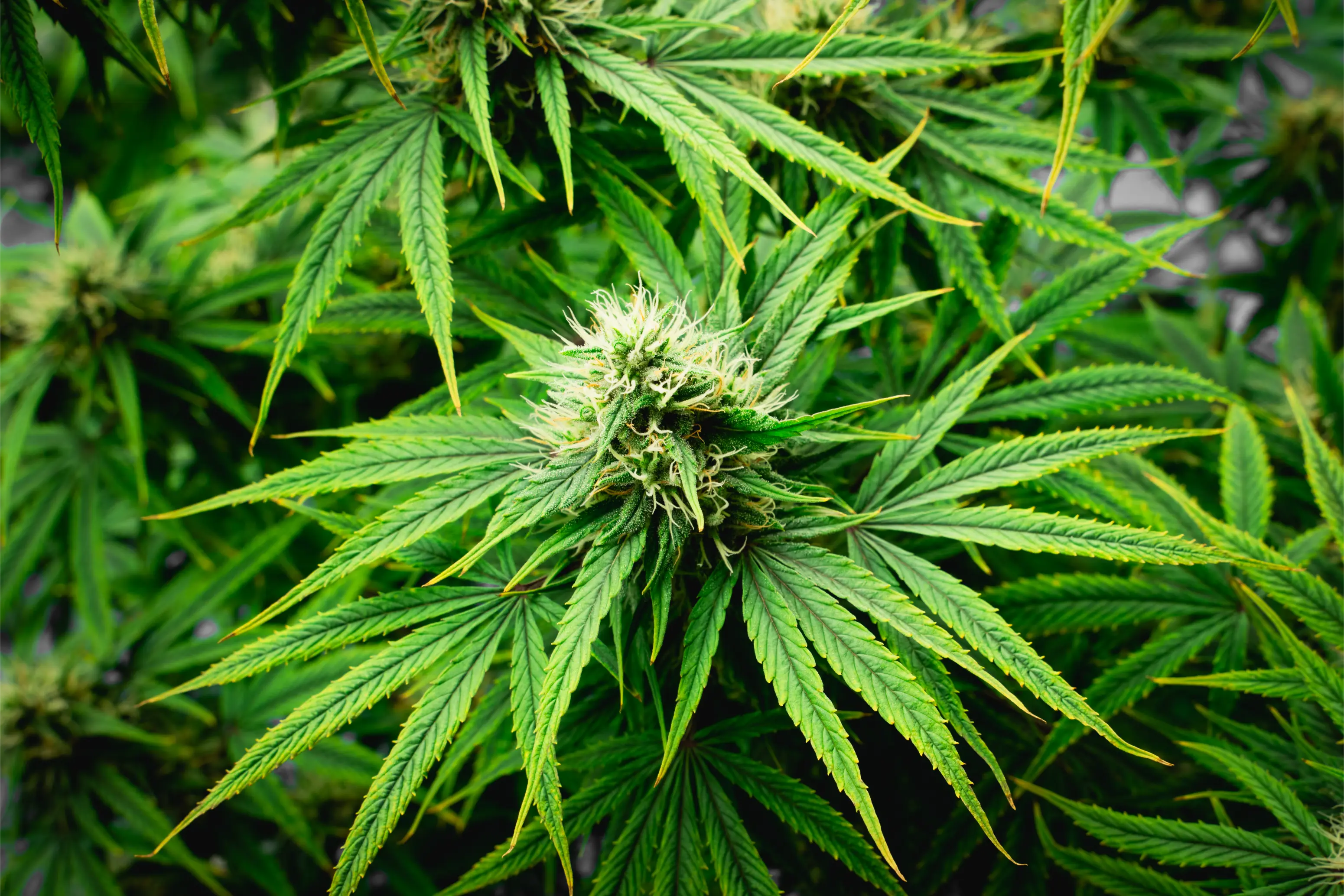
CO2 Controller and Sensor Placement
In modern controlled environment agriculture, supplemental carbon dioxide is one of the most powerful and expensive inputs a cultivator can deploy. Elevating atmospheric carbon dioxide from the ambient baseline of 415 parts per million (ppm) to therapeutic horticultural concentrations between 1,000 and 1,500 ppm increases canopy photosynthesis by up to 35 percent, accelerating floral biomass accumulation and maximizing dry harvest weight. However, the biological efficiency, chemical safety, and operational cost of carbon dioxide enrichment depend entirely on the fidelity of the environmental sensor and its physical location within the growing space.
Carbon dioxide is an invisible, odorless compressed gas governed by strict thermodynamic and fluid-dynamic properties. With a molecular weight of 44.01 grams per mole, pure carbon dioxide is roughly 1.52 times denser than standard atmospheric air (28.97 grams per mole). If an indoor cultivation suite lacks adequate mechanical circulation, injected gas naturally sinks toward the floor, forming stagnant, high-concentration pools that starve the upper canopy leaves while creating false, skewed readings on environmental controllers. Conversely, if an optical sensor is positioned directly in front of an air conditioning supply diffuser, an oscillating fan blast, or a gas injection nozzle, the controller receives localized, highly distorted data that causes short-cycling of injection solenoids and massive gas wastage.
Fluid Dynamics Principle: Thermal Turbulence vs Molecular Stratification
A widespread misconception in indoor horticulture is that carbon dioxide permanently separates from ambient air and settles on the floor like liquid water. In classical physics, Dalton Law of Partial Pressures and Graham Law of Diffusion dictate that once gas molecules mix through mechanical turbulence, they do not spontaneously unmix based on molecular weight alone. In an active cannabis room equipped with horizontal circulation fans, air currents easily overpower gravitational settling. However, whenever air circulation stops or microclimate dead zones exist, cold, freshly injected gas immediately sinks. Correct sensor placement must capture active canopy assimilation under dynamic airflow while avoiding stagnant low-pressure pockets.
Furthermore, the physical construction of the sensor itself dictates its operational lifespan and measurement precision. The vast majority of low-cost horticultural sensors utilize single-beam Non-Dispersive Infrared (NDIR) optical benches governed by Automatic Baseline Calibration (ABC) algorithms. In an enriched cultivation room where carbon dioxide never drops to ambient outdoor levels (400 ppm), ABC algorithms falsely recalibrate the sensor baseline upward, blinding the controller and drifting actual room concentrations into phytotoxic and dangerous ranges. Mastering commercial CO2 control requires deploying dual-beam NDIR optics, proper vertical suspension geometry, and strict photoperiod electrical interlocking.
This comprehensive engineering manual delivers an exhaustive technical breakdown of carbon dioxide controller architecture and sensor placement geometry. Cultivators will master the physics of optical gas detection, canopy height adjustment protocols, microclimate interference mitigation, electrical failsafe interlocking, empty-room sensor commissioning, and multi-point calibration routines necessary to achieve rock-solid atmospheric control.
NDIR Sensor Physics: Single-Beam vs Dual-Beam Optical Benches
To Understand Why Sensor Placement
To understand why sensor placement is so unforgiving, cultivators must examine the optical physics of Non-Dispersive Infrared (NDIR) detection. Carbon dioxide molecules absorb electromagnetic radiation at very specific infrared wavelengths, most notably at 4.26 micrometers (μm). An NDIR optical sensor consists of a miniature infrared incandescent or micro-electromechanical system (MEMS) light source, a sealed optical absorption sample chamber through which ambient room air passively diffuses, a narrow-band optical interference filter, and an infrared photodetector.
When the internal light source pulses infrared radiation through the sample chamber, carbon dioxide molecules absorb a fraction of the 4.26 μm light proportional to their atmospheric concentration. The mathematical relationship governing this attenuation is described by the Beer-Lambert Law of optical absorption, expressed as I equals I_0 multiplied by the natural exponential of negative alpha times concentration times path length. The photodetector measures the remaining light intensity, which the controller microprocessor converts into a digital parts-per-million reading. The crucial engineering distinction between sensor models lies in how the device compensates for optical aging, dust accumulation, barometric shifts, and thermal drift:
“When working on to understand why sensor placement in my home grow, how do I know if my current setup is drifting out of range before visible plant stress appears?”
Question sent by: Brody Ouellet, via email.
Start by taking a direct baseline measurement rather than guessing from foliar symptoms alone. In practice, When the internal light source pulses infrared radiation through the sample chamber, carbon dioxide molecules absorb a fraction of the 4.26 μm light proportional to their atmospheric concentration.
Once you have confirmed the baseline reading, adjust only one variable at a time and log the response over the next 24 to 48 hours. Enclosed dual-beam chambers with sealed optical bandpass filters ensure that only the exact 4.26 μm resonance band is registered by the detector.
Industrial Sensors Must Be Fitted
In addition to dual-beam optics, industrial sensors must be fitted with a breathable, hydrophobic polytetrafluoroethylene (PTFE) or sintered stainless steel particulate filter screen. High-humidity cultivation environments generate airborne aerosolized nutrient salts, organic dust, and insect debris. Without an intact hydrophobic filter membrane, moisture condenses on the cold internal gold-plated mirrors of the optical chamber, causing severe optical scattering and permanent sensor destruction.
Field Verification Checklist
- Single-Beam NDIR Sensors: These sensors utilize a single optical channel and a single photodetector. Over weeks of operation, microscopic dust coats the internal mirrors, the infrared lamp output degrades, and temperature fluctuations shift detector sensitivity. To counteract this natural downward drift, manufacturers embed an Automatic Baseline Calibration (ABC) software algorithm. The algorithm assumes that every seven to fourteen days, the room will be empty and carbon dioxide levels will drop to ambient outdoor baseline (400 to 420 ppm). In an enriched cannabis room running 1,200 ppm continuously, the ABC algorithm falsely assumes that 1,200 ppm is the new 400 ppm baseline! Over several weeks, actual room concentrations climb to dangerous levels (2,500 to 3,500 ppm) while the display continues falsely reading 1,200 ppm.
- Dual-Beam NDIR Sensors: Commercial-grade horticultural controllers utilize dual-beam (dual-wavelength) NDIR technology. These advanced optical benches measure two distinct wavelengths simultaneously: an active absorption channel at 4.26 μm (measuring CO2 attenuation) and a reference channel at 3.91 μm (a neutral infrared wavelength where no atmospheric gases absorb light). Because dirt accumulation, lamp aging, and optical degradation affect both channels equally, the controller microprocessor continuously compares the ratio between the two signals. This optical referencing eliminates baseline drift without relying on flawed ABC algorithms, maintaining precision within plus or minus 30 ppm over multi-year operational cycles.
- Barometric Pressure and Altitude Compensation: Optical absorption is fundamentally a measure of molecular density rather than volumetric concentration alone. As barometric pressure changes with weather fronts or facility elevation above sea level, the number of gas molecules per unit volume shifts according to the Ideal Gas Law. At an elevation of 5,000 feet (1,524 meters), standard atmospheric pressure drops from 101.3 kPa down to roughly 84.3 kPa. An uncompensated NDIR sensor calibrated at sea level will under-report actual parts per million by roughly 17 percent. Industrial controllers incorporate an integrated barometric pressure transducer that continuously corrects the optical absorption curve in real time.
Furthermore, volatile organic compounds (VOCs) and secondary botanical aerosols emitted by the cannabis crop itself can interfere with low-grade sensors. During the late floral swelling phase, mature female inflorescences release heavy concentrations of volatile monoterpenes and sesquiterpenes, including beta-myrcene, alpha-pinene, and beta-caryophyllene. In sub-standard optical benches lacking narrow-band optical interference filters, high ambient terpene concentrations can cause spectral overlap and cross-sensitivity, leading to erratic concentration spikes. Enclosed dual-beam chambers with sealed optical bandpass filters ensure that only the exact 4.26 μm resonance band is registered by the detector.
Vertical and Horizontal Placement Geometry within the Canopy
The Physical Location of the Carbon Dioxide
The physical location of the carbon dioxide sensor within the three-dimensional room volume determines whether the environmental automation system maintains a stable, uniform microclimate or cycles chaotically. Cultivators must follow strict spatial coordinates when positioning the sensing module:
Vertical Height Coordination. The sensor must always be suspended at the active mid-canopy level, specifically within the top one-third of the plant height where the highest concentration of mature, light-saturated sun leaves reside. In vegetative growth, this may position the sensor 24 to 36 inches above the floor or container surface; during peak mid-flowering, the sensor must be raised to 48 to 60 inches above the floor. If the sensor is mounted too high (above the light fixtures), it measures hot, buoyant convective air that has collected heat from LED power supplies, reading an artificially diluted CO2 level. If mounted too low (below the dense under-canopy foliage), it reads stagnant floor-level gas that has not mixed with the active transpirational air stream.
“I am trying to dial in the physical location of the carbon dioxide for my indoor tent, what is the most reliable measurement to check first so I do not overcorrect?”
Question sent by: CalgaryClosetCraft, via contact form.
Start by taking a direct baseline measurement rather than guessing from foliar symptoms alone. In practice, In vegetative growth, this may position the sensor 24 to 36 inches above the floor or container surface; during peak mid-flowering, the sensor must be raised to 48 to 60 inches above the floor.
Once you have confirmed the baseline reading, adjust only one variable at a time and log the response over the next 24 to 48 hours. When air velocity across the foliage is insufficient (below 0.15 m/s), the boundary layer thickens to several millimeters, creating extreme boundary layer resistance (rb) that starves the mesophyll cells of carbon dioxide even if bulk room air reads 1,200 ppm.
To maintain proper vertical geometry as plants stretch, the sensor must never be screwed rigidly to a fixed wall. Instead, suspend the sensor from an overhead ratchet hanger or motorized lift cable that allows daily or weekly micro-adjustments. The sensor probe should sit approximately 6 to 12 inches below the highest floral colas, directly within the zone of maximum Photosynthetic Photon Flux Density (PPFD).
Canopy Mechanics: The Importance of Continuous Height Recalibration
During the explosive flowering stretch (weeks one through three of the 12/12 photoperiod), vigorous sativa-dominant and hybrid cannabis cultivars can stretch between 1.5 and 2.5 inches per day. If a cultivator leaves the CO2 sensor at its initial vegetative mounting height, the rapidly expanding floral canopy will engulf and bury the sensor within dense lower foliage within ten days. Deep inside the shaded under-canopy, low light levels prevent active photosynthetic carboxylation, allowing respiratory CO2 to accumulate. The buried sensor reads an artificially high concentration (e.g., 1,400 ppm) and shuts off gas injection, while the blazing upper sun leaves 30 inches above starve in a depleted 500 ppm atmosphere. Check and adjust sensor height twice weekly throughout the stretch.
Horizontal Placement and Airflow Dynamics.
Horizontal Placement and Airflow Dynamics. Horizontally, the sensor must be positioned centrally within the active plant canopy, away from boundary walls and physical obstacles. However, the probe must be placed within a gentle, laminar air stream moving at 0.3 to 0.5 meters per second (60 to 100 feet per minute). Moving air is mandatory because carbon dioxide diffuses into the NDIR optical chamber through passive diffusion holes. If the sensor is hung in a dead-air pocket behind a carbon filter or between overlapping fan leaves, the local gas concentration inside the diffusion chamber lags behind the true room concentration by fifteen to twenty minutes, causing severe controller hunting and overshooting.
Air Movement Across the Canopy Foliage Also
Air movement across the canopy foliage also plays a direct physiological role in gas assimilation. Surrounding every cannabis leaf is a microscopic layer of motionless air known as the boundary layer. Stomata located on the abaxial (underside) leaf surface must pull carbon dioxide through this boundary layer via molecular diffusion. When air velocity across the foliage is insufficient (below 0.15 m/s), the boundary layer thickens to several millimeters, creating extreme boundary layer resistance (rb) that starves the mesophyll cells of carbon dioxide even if bulk room air reads 1,200 ppm. Sustaining 0.3 to 0.5 m/s air velocity thins the boundary layer to under 0.8 millimeters, maximizing stomatal conductance and ensuring that the concentration measured by the sensor accurately mirrors the concentration entering the leaf interior.
| Sensor Placement Zone | Microclimate Condition | Controller Response Error | System Consequence |
|---|---|---|---|
| Directly beneath LED Driver | Excess sensible heat; thermal updraft | Reads artificially low CO2 (air expansion) | Over-injects gas; excessive fuel consumption |
| In front of Dehumidifier Outflow | Super-heated, dry air blast (35°C) | High temperature drift; distorted RH | Unstable solenoid cycling; rapid hunting |
| Under Lower Canopy Foliage | Shaded dead zone; plant dark respiration | Reads artificially high CO2 (pooling) | Under-injects gas; canopy starves for carbon |
| Beside Entry Doorway | Ambient room air infiltration; drafts | Constant 400-500 ppm reading during entry | Continuous injection; dumps gas outdoors |
| Top 1/3 Canopy in Laminar Flow | Active photosynthetic absorption zone | Accurate real-time canopy assimilation | Stable ±30 ppm control; optimal yield |
The table above illustrates the catastrophic microclimate traps that sabotage environmental automation. Mounting a sensor in any of the four incorrect zones corrupts the entire cultivation cycle, wasting thousands of dollars in compressed gas or tripping false safety alarms.
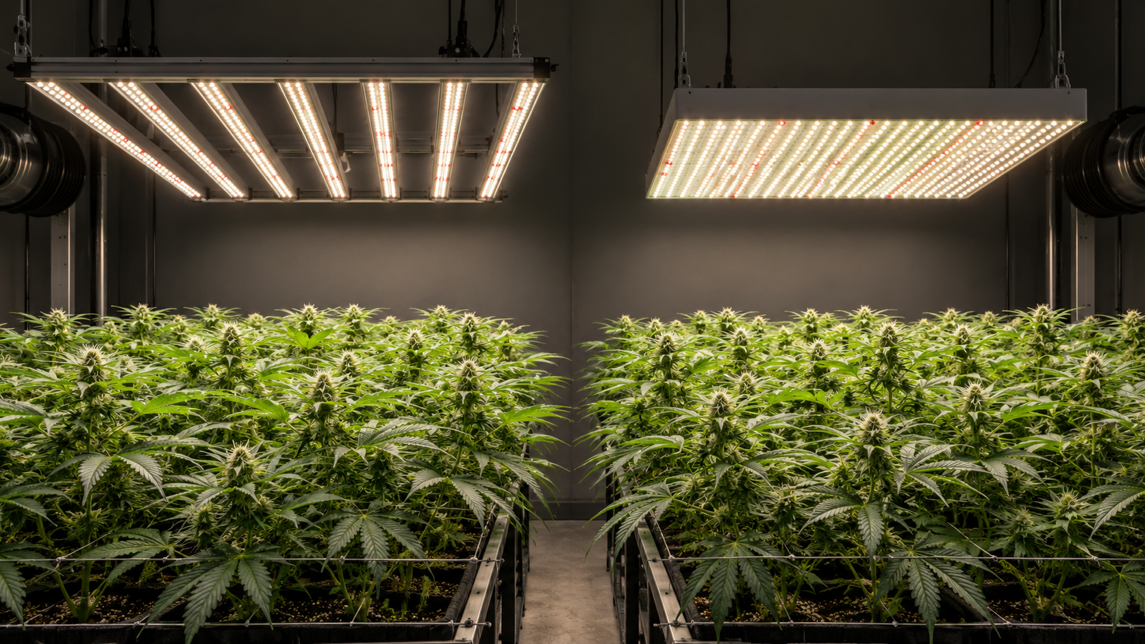
In large commercial facilities with multiple growing benches, relying on a single sensing point creates dangerous environmental blind spots. Variations in ceiling height, ductwork discharge velocities, and plant canopy densities inevitably create microclimate gradients across large rooms. Commercial environmental automation platforms solve this by deploying multi-sensor averaging networks. Three to six dual-beam NDIR sensor modules connected via Modbus RTU (RS-485) or 0-10V industrial analog loops are distributed symmetrically across the canopy. The central automation computer calculates a weighted spatial average to drive injection solenoids, while alerting cultivators if any single zone drifts more than 150 ppm from the room mean, identifying localized circulation failures or clogged distribution emitters.
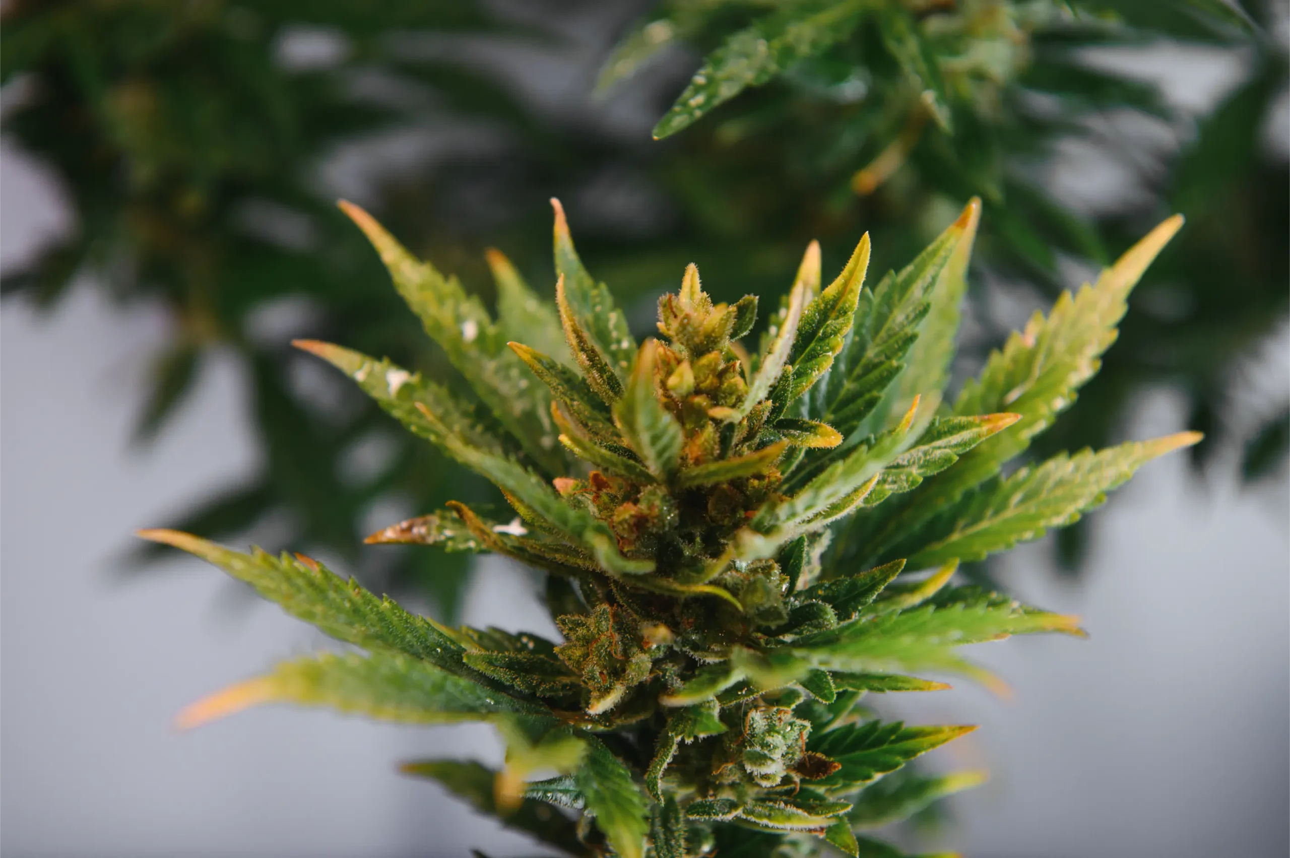
Microclimate Interference: Avoiding Heat, Moisture, and Direct Injection Plumes
Environmental Sensors Deployed in High-performance Grow Rooms
Environmental sensors deployed in high-performance grow rooms operate in extreme, hostile microclimates. Commercial cannabis rooms routinely combine high relative humidity (60 to 75 percent), high air velocities from circulation fans, intense radiant photon bombardment, and localized thermal emissions. Cultivators must protect the NDIR optical chamber from three major sources of microclimate interference:
Interference 1: Radiant Thermal Loading. Modern high-output LED fixtures generate intense photon energy, delivering PPFD levels between 900 and 1,500 μmol/m²/s. If an NDIR sensor housing made of black or dark plastic is hung directly under an unshielded light bar, the radiant energy heats the internal sensor housing up to 10 degrees Celsius above the ambient air temperature. Because gas density is inversely proportional to absolute temperature (according to Charles Law), heating the air inside the optical chamber reduces the number of gas molecules occupying the sample path. The sensor interprets this reduced molecule count as a lower CO2 concentration, falsely triggering unnecessary gas injection. Cultivators must install a reflective aluminum or bright white aspirating sunshield over the sensor body, or utilize a controller with an integrated aspirated fan shield that draws continuous ambient air across the internal optical bench.
Interference 2: Direct Gas Injection Plumes.
Interference 2: Direct Gas Injection Plumes. The sensor must never be located downstream of, or in line of sight with, the carbon dioxide injection source. If compressed gas is distributed through overhead laser-perforated polyurethane tubing, ensure that no emitter hole points directly at the sensor. A direct plume of expanding gas will instantly register as 3,000 to 5,000 ppm on the controller, shutting off the solenoid valve while the rest of the room sits at 600 ppm. The sensor should be placed at least 8 to 10 feet horizontally away from the primary gas discharge point, positioned in the return circulation path where the gas has already fully homogenized with the ambient air mass.
“Should I mount my CO2 sensor on the wall near my environmental controller, or should it always be suspended over the plants?”
Question sent by: Brody Gallagher, via grow journal submission.
You must never rely on a wall-mounted sensor to control carbon dioxide enrichment in a plant canopy. Boundary walls in indoor grow rooms suffer from severe microclimate drag. Air moving across smooth reflective wall panels experiences frictional deceleration, creating a stagnant boundary layer where air velocity drops to near zero. Furthermore, exterior perimeter walls often conduct thermal energy from outdoors, creating localized cold spots in winter or hot radiant thermal zones in summer that distort temperature and humidity measurements.
Most importantly, walls are separated from the active transpirational and photosynthetic flux of the crop. The plants do not grow on the wall; they live in the center of the room. A wall sensor will always register delayed, dampened readings. Always utilize a remote sensor probe connected via a shielded communication cable and suspend it directly above the center of the plant canopy on an adjustable ratchet hanger. The only sensors that should be mounted on walls are secondary life-safety evacuation monitors placed 12 to 18 inches above the floor near the doorway.
Interference 3: Direct Ultrasonic and Evaporative Humidity Plumes.
Interference 3: Direct Ultrasonic and Evaporative Humidity Plumes. If the facility utilizes commercial ultrasonic humidifiers or high-pressure aeroponic foggers, the sensor must be kept well away from the aerosolized vapor plume. Ultrasonic humidifiers atomize liquid water into microscopic water droplets (1 to 5 microns). If these cold, liquid water droplets enter the NDIR optical chamber, they scatter the infrared beam, creating false attenuation that the microprocessor registers as massive CO2 spikes. Ensure humidifiers discharge into the main air-handling supply duct or into the turbulent intake of an oscillating circulation fan, allowing moisture to evaporate fully into transparent water vapor before reaching the canopy sensor.
Additionally, localized microclimate condensations can occur if the room experiences sudden temperature drops at the beginning of the dark cycle. If warm, moisture-laden air (e.g., 26°C at 70 percent RH) contacts a cold metal sensor body or uninsulated cable drop, the surface temperature can plunge below the dew point (20°C), depositing liquid water directly onto the sensor diffusion port. High-end horticultural sensors mitigate this by incorporating a low-wattage internal heating resistor that keeps the optical housing slightly above the ambient dew point, permanently preventing internal lens fogging and corrosion.
Photoperiod Synchronization and Electrical Failsafe Interlocking
Carbon Dioxide Enrichment
Carbon dioxide enrichment is strictly a light-dependent biological process. Under the light-dependent reactions of photosynthesis, chlorophyll absorbs photons to split water molecules (photolysis), generating Adenosine Triphosphate (ATP) and Nicotinamide Adenine Dinucleotide Phosphate (NADPH). These high-energy chemical intermediates power the light-independent Calvin cycle, where the enzyme RuBisCO fixes atmospheric carbon dioxide into 3-phosphoglycerate and ultimately synthesized carbohydrates.
Field Verification Checklist
- Photocell / Light Sensor Interlock: Every horticultural carbon dioxide controller must be equipped with an integrated optical photocell or hardwired relay interlock connected to the lighting timer. The moment ambient light levels drop below 5 foot-candles (50 lux), the controller must de-energize the gas injection solenoid and disable all enrichment logic. Supplementing CO2 in the dark wastes 100 percent of the injected gas, accelerates cylinder depletion, and increases room humidity.
- Nighttime Toxic Accumulation Hazards: Because mature flowering canopies actively respire in the dark, carbon dioxide concentrations in an unventilated sealed room can naturally climb from 800 ppm at lights-out up to 1,800 or 2,200 ppm by morning purely from biological respiration. If an uncontrolled solenoid continues dosing gas during the night, atmospheric concentrations can easily surpass 3,500 ppm, acidifying the root zone substrate and displacing oxygen from the root boundary layer.
- Normally-Closed Solenoid Valve Wiring: The delivery solenoid valve must always be plumbed and wired in a normally-closed (NC) configuration. In the event of a utility power outage, an emergency shutdown, or a blown fuse on the controller circuit board, the magnetic coil instantly de-energizes and an internal mechanical spring snaps the valve shut. Never install normally-open valves or motorized ball valves that fail in their last known position.
The Moment the Grow Lights Turn Off
The moment the grow lights turn off and the photoperiod enters the dark cycle, the light-dependent reactions cease instantaneously. ATP and NADPH generation halts, RuBisCO shuts down, and the cannabis plant completely stops absorbing atmospheric carbon dioxide. In fact, during the night cycle, cannabis transitions entirely to mitochondrial respiration, consuming ambient oxygen and actively emitting carbon dioxide through stomata as it metabolizes stored carbohydrates for cellular maintenance and tissue expansion.
“My grow room logs look stable on paper, but I am still unsure about carbon dioxide enrichment. Should I adjust my equipment settings immediately or run a baseline verification test first?”
Question sent by: Brody Blais, via contact form.
Start by taking a direct baseline measurement rather than guessing from foliar symptoms alone. In practice, Commercial automation systems utilize a binary lockout circuit: whenever the exhaust damper motor or purge fan contactor receives an enable command, the CO2 injection circuit is forcibly opened, locking out the solenoid until the purge cycle terminates and the room returns to a fully sealed state.
Once you have confirmed the baseline reading, adjust only one variable at a time and log the response over the next 24 to 48 hours. Gradual, single-variable corrections protect root function and canopy stability without triggering secondary shock.
In automated HVACD architectures where exhaust fans or economizer dampers cycle periodically to purge excess heat or humidity, the carbon dioxide controller must be electronically interlocked with the ventilation dampers. Operating an enrichment solenoid while motorized exhaust dampers are open creates an open-loop bypass: pure compressed gas is injected at one end of the room and sucked out into the building exhaust duct within two minutes. Commercial automation systems utilize a binary lockout circuit: whenever the exhaust damper motor or purge fan contactor receives an enable command, the CO2 injection circuit is forcibly opened, locking out the solenoid until the purge cycle terminates and the room returns to a fully sealed state.
Commissioning Protocols and Sensor Calibration Workflows
Before Relying on Any New Carbon Dioxide
Before relying on any new carbon dioxide control installation, cultivators must execute a multi-step commissioning protocol to verify sensor accuracy, response hysteresis, and failsafe integration:
Field Advice: Root-Zone Physiology: Carbon Dioxide Toxicity in the Rhizosphere. While foliar canopies thrive under 1,200 ppm CO2 during active photoperiods, plant root zones require continuous dissolved oxygen (DO) to support active ion transport and cellular respiration. When nighttime carbon dioxide accumulates unchecked, dense gas settles into container media and hydroponic drain tables. Excessive carbonic acid forms in wet root zones, dropping substrate pH and suffocating beneficial rhizosphere aerobic microbes. Enforcing strict photoperiod lockouts protects root-zone metabolic health and prevents pythium outbreaks.
Step 1: Outdoor Fresh-Air Zero Verification. Take the disconnected sensor module outdoors into clean, fresh ambient air on a clear day, away from vehicle exhaust, building ventilation louvers, and human breath. Power the sensor using a portable battery pack or temporary extension lead and allow it to stabilize for fifteen minutes. Standard outdoor atmospheric carbon dioxide hovers consistently between 415 and 425 ppm. If the sensor displays a reading outside 390 to 440 ppm, perform a manual single-point fresh-air calibration according to the manufacturer technical manual. Never perform a fresh-air calibration indoors or inside a sealed vehicle.
Step 2: Dual-Point Span Calibration (Commercial Facilities).
Step 2: Dual-Point Span Calibration (Commercial Facilities). For licensed commercial facilities requiring certified environmental audit compliance, conduct a certified two-point span calibration every six months. Connect a zero-calibration gas cylinder containing 99.99 percent pure nitrogen (0 ppm CO2) to the sensor calibration hood at a regulated flow rate of 0.5 liters per minute for three minutes to establish the zero datum. Next, connect a certified span gas cylinder containing exactly 1,000 ppm CO2 balanced in nitrogen to verify the optical gain curve. Adjust the microprocessor span calibration potentiometer or digital register until the displayed reading matches the certified span bottle concentration within plus or minus 10 ppm.
Step 3: Response Hysteresis and Controller Tuning. Reinstall the sensor at canopy level. Configure the controller deadband (hysteresis) settings. The deadband prevents rapid solenoid chatter by establishing an activation threshold and a deactivation threshold. For example, if the target concentration is 1,200 ppm with a 50 ppm deadband, the controller should open the solenoid when levels drop to 1,150 ppm and close the valve when levels reach 1,200 ppm. In large rooms, gas distribution delays require adding an injection delay timer (e.g., inject for 60 seconds, then pause for 3 minutes to allow circulation fans to mix the air mass before the sensor samples again).
Preventative Maintenance and Recheck Schedule
Optical Sensors Are Sensitive Analytical Instruments
Optical sensors are sensitive analytical instruments that require routine servicing to maintain high accuracy and prevent premature failure. Cultivators should follow this structured maintenance matrix throughout the crop lifecycle:
| Service Frequency | Inspection and Maintenance Task | Acceptable Measurement Criteria | Corrective Action if Failed |
|---|---|---|---|
| Daily | Visual check of sensor canopy clearance and display | Sensor probe sits 6-12 inches below top colas | Adjust suspension ratchet hanger as canopy stretches |
| Weekly | Verify photocell night-mode shutdown | Controller display indicates NIGHT; solenoid inactive | Clean photocell optic lens; adjust lux sensitivity threshold |
| Monthly | Cross-check with calibrated handheld NDIR meter | Controller and handheld agree within ±50 ppm | Flag sensor for recalibration; clean optical dust filter |
| Every 90 Days | Outdoor fresh-air calibration check | Sensor reads 415 ± 20 ppm in clean outdoor air | Execute manual fresh-air zero calibration routine |
| Between Harvests | Deep sanitation and particulate filter replacement | Clean, debris-free sensor casing; intact PTFE membrane | Replace clogged sintered filter screen; wipe body with isopropyl |
| Annually | Certified span gas audit and solenoid valve rebuild | ±2% accuracy against certified 1,000 ppm span gas | Factory rebuild of optical chamber or replace sensor head |
By Enforcing Disciplined Spatial Placement Selecting Dual-beam
By enforcing disciplined spatial placement, selecting dual-beam NDIR optics, and maintaining routine calibration schedules, cultivators can eliminate environmental blind spots, maximize carbon assimilation efficiency, and harvest heavy, resinous canopies cycle after cycle.
Scientific References
- Both, A. J., Benjamin, L., Albright, L. D., & Holmgren, M. (2015). Greenhouse temperature, humidity, and carbon dioxide sensing and control. Acta Horticulturae, 1107, 35-44.
- Chandra, S., Lata, H., Khan, I. A., & ElSohly, M. A. (2008). Photosynthetic plasticity in Cannabis sativa L. to elevated atmospheric carbon dioxide and temperature. Photosynthetica, 46(4), 578-585.
- Bugbee, B. (2016). Toward an optimal spectral quality for plant growth and development: The importance of radiation capture. Frontiers in Plant Science, 7, 1073.
- Kramer, P. J., & Boyer, J. S. (1995). Water Relations of Plants and Soils. San Diego, CA: Academic Press.
- National Institute for Occupational Safety and Health (NIOSH). (2018). Occupational Safety and Health Guideline for Carbon Dioxide. Cincinnati, OH: U.S. Department of Health and Human Services.
- Ting, K. C., & Giacomelli, G. A. (1991). Measurement and control of greenhouse environments. In Automated Agriculture for the 21st Century (pp. 382-390). St. Joseph, MI: ASAE.
Share this article
A quick overview of the topics covered in this article.
Follow us
Latest articles

November 7, 2026
November 7, 2026
November 7, 2026

November 7, 2026